


Optimal Nozzle Arrangement for Phosphating Cleaning in Automotive Coating Pre-Treatment
Table of Contents
- Table of Contents
- 1. Introduction: Why Nozzle Arrangement Determines Phosphating Quality
- 2. Critical Parameters in Phosphating Spray Coverage
- 2.1 Impact Force and Surface Wetting
- 2.2 Droplet Size and Chemical Adhesion Time
- 2.3 Coverage Uniformity and Overlap Ratio
- 3. Nozzle Type Selection for Phosphating Stages
- 3.1 Pre-Cleaning and Degreasing
- 3.2 Phosphating Application
- 3.3 Post-Rinse
- 3.4 Stage-by-Stage Comparison Table
- 4. Optimal Nozzle Spacing and Overlap Calculation
- 4.1 Theoretical Spacing Formula
- 4.2 Correction Factors for Automotive Body Geometry
- 4.3 Vertical Staggering to Eliminate Shadow Zones
- 4.4 Worked Example: Calculating Full Bank Layout
- 5. Vertical and Horizontal Arrangement Patterns
- 5.1 Single-Level vs Multi-Level Banks
- 5.2 In-Line vs Staggered Opposing Banks
- 5.3 Pattern Comparison Table
- 5.4 Special Considerations for SUV and Truck Bodies
- 6. Common Installation Mistakes and Field Corrections
- 6.1 Mistake #1: Using Catalog Spray Angle Without Pressure Verification
- 6.2 Mistake #2: Ignoring Nozzle Wear Impact on Pattern
- 6.3 Mistake #3: Symmetrical Arrangement for Asymmetrical Bodies
- 6.4 Mistake #4: Inadequate Drainage Provision
- 6.5 Troubleshooting Matrix
- 7. Maintenance and Performance Monitoring
- 7.1 Preventive Maintenance Schedule
- 7.2 Performance Metrics to Track
- 7.3 Validation Methods
- 8. FAQ
- Q1: Can I use the same nozzle arrangement for all body styles on a mixed-model line?
- Q2: How much pressure drop should I expect along a 2-meter nozzle manifold?
- Q3: Should I use air-atomizing or hydraulic nozzles for phosphating?
- Q4: How do I know when nozzles need replacement—flow rate or spray angle?
- Q5: What's the ROI of upgrading from stainless steel to ceramic nozzles in phosphating?
- 9. Conclusion and Next Actions
- Next Actions
Table of Contents
- Introduction: Why Nozzle Arrangement Determines Phosphating Quality
- Critical Parameters in Phosphating Spray Coverage
- Nozzle Type Selection for Phosphating Stages
- Optimal Nozzle Spacing and Overlap Calculation
- Vertical and Horizontal Arrangement Patterns
- Common Installation Mistakes and Field Corrections
- Maintenance and Performance Monitoring
- FAQ
- Conclusion and Next Actions
1. Introduction: Why Nozzle Arrangement Determines Phosphating Quality
In automotive body pre-treatment lines, phosphating quality directly impacts coating adhesion, corrosion resistance, and ultimately warranty claims. From our field experience across 50+ OEM and Tier-1 coating lines, poor nozzle arrangement is responsible for approximately 60% of phosphating defects—far exceeding issues from chemistry concentration or temperature control.
The challenge is that automotive bodies have complex geometries: roof channels, door hems, rocker panels, and box sections. Standard flat fan nozzles arranged in a single plane cannot deliver uniform chemical contact across these surfaces. This guide provides engineering-level calculations and field-proven arrangement patterns that achieve 95%+ surface coverage while optimizing chemical consumption and minimizing overspray.
What you will learn: How to calculate nozzle spacing based on spray angle and target distance; vertical staggering patterns that eliminate shadow zones; the critical difference between pre-cleaning, phosphating, and rinse stage arrangements; how to validate coverage using water-sensitive paper or fluorescent tracer testing; and how to reduce chemical waste by 15–25% through optimized overlap ratios.
This is not a nozzle catalog. This is a field application engineer's handbook based on actual installation data, coverage mapping results, and troubleshooting from production environments.
2. Critical Parameters in Phosphating Spray Coverage
2.1 Impact Force and Surface Wetting
Phosphating requires sufficient impact force to displace air pockets and ensure chemical contact with the metal substrate. In our testing, flat fan nozzles at 30–45 PSI deliver 0.15–0.25 N/cm² impact force at 300mm distance—adequate for vertical panels but marginal for inverted surfaces like door undersides.
Full cone nozzles at equivalent flow rates produce 40% higher impact force but consume 20–30% more chemical due to wider spray dispersion. For critical areas (wheel arches, rocker inners), we recommend dedicated full cone nozzles at 45–60 PSI, while flat fans handle open body panels at 30–40 PSI.
Key takeaway: Match nozzle type to surface orientation and accessibility, not just to achieve "full coverage."
2.2 Droplet Size and Chemical Adhesion Time
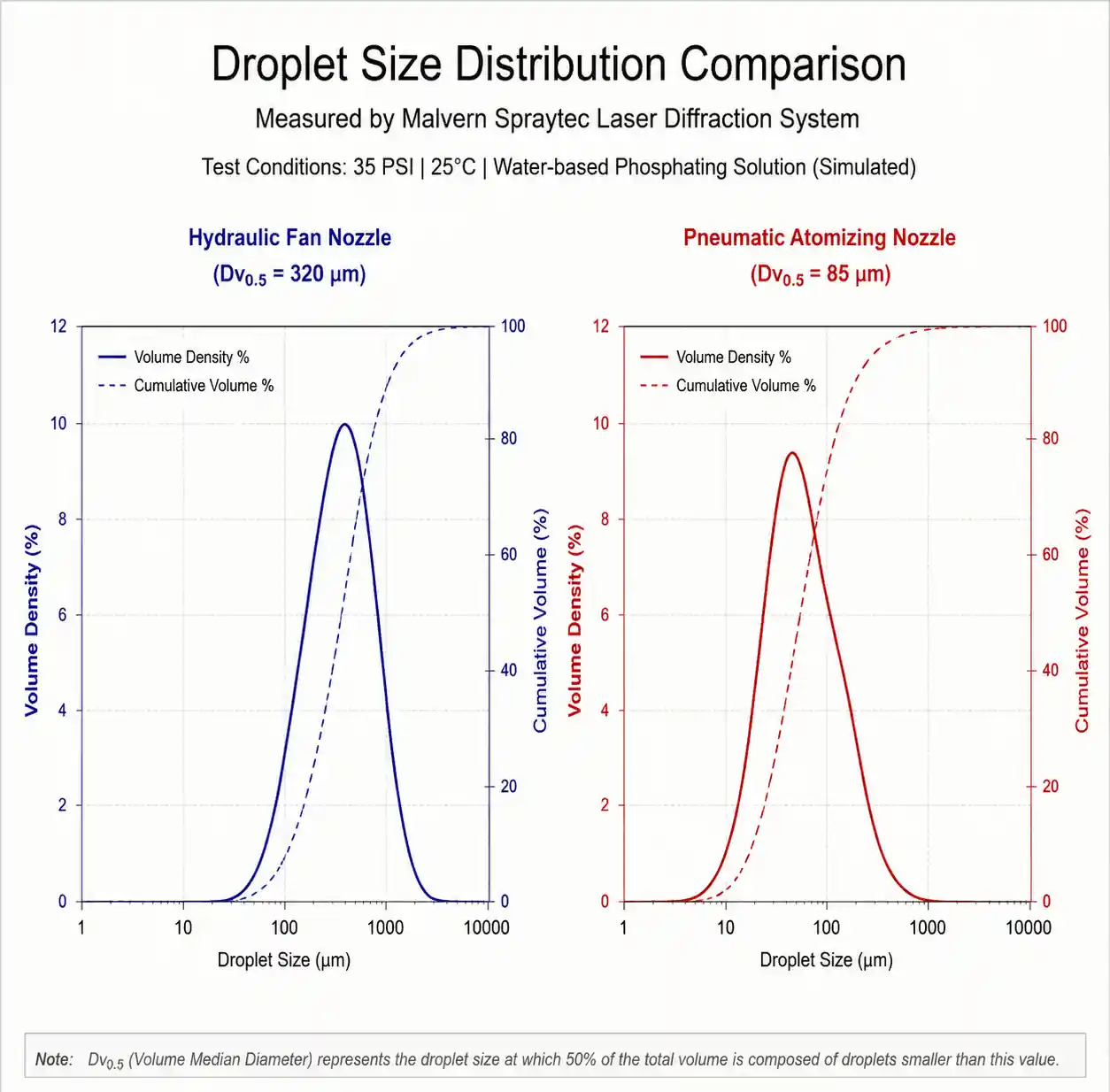
Phosphating chemistry requires 2–5 seconds contact time at 45–60°C. Droplet size directly affects this: 200–400 micron droplets provide adequate mass and residence time, while sub-100 micron mist evaporates or drains too quickly on vertical surfaces.
From laser diffraction analysis (Malvern Spraytec), hydraulic flat fan nozzles at 35 PSI produce Dv0.5 of 280–350 microns—ideal for phosphating. Air-atomizing nozzles (often used in final rinse) produce 50–120 micron droplets and should NOT be used in phosphating zones due to insufficient wetting.
2.3 Coverage Uniformity and Overlap Ratio
Single-pass coverage tests using water-sensitive paper show that isolated nozzles leave dry strips between spray edges. Achieving uniform coverage requires 30–50% overlap between adjacent spray patterns.
Overlap calculation:
- Spray width at target distance: W = 2 × D × tan(θ/2)
- Required nozzle spacing: S = W × (1 - overlap ratio)
- Example: 80° flat fan at 300mm distance → W = 2 × 300 × tan(40°) ≈ 503mm
- For 40% overlap: S = 503 × 0.6 ≈ 300mm
However, this assumes perpendicular incidence and flat target geometry—rarely true in automotive bodies. Actual spacing must account for body curvature and multi-plane nozzle banks.
3. Nozzle Type Selection for Phosphating Stages
Different pre-treatment stages demand different spray characteristics. Mismatching nozzle type to stage function is the most common specification error we encounter.
3.1 Pre-Cleaning and Degreasing
Recommended: Hydraulic flat fan nozzles, 40–80° spray angle, 40–60 PSI, stainless steel 316 construction.
Reasoning: High impact force needed to remove stamping oils and weld spatter. Flat fan pattern provides controlled strip coverage with minimal chemical waste. At 50 PSI, impact force reaches 0.3 N/cm² at 250mm—sufficient to dislodge particulates without damaging zinc coating on galvanized steel.
Typical arrangement: Vertical banks with 25° downward tilt, 250–300mm spacing, staggered left/right by 125–150mm between opposing banks.
3.2 Phosphating Application
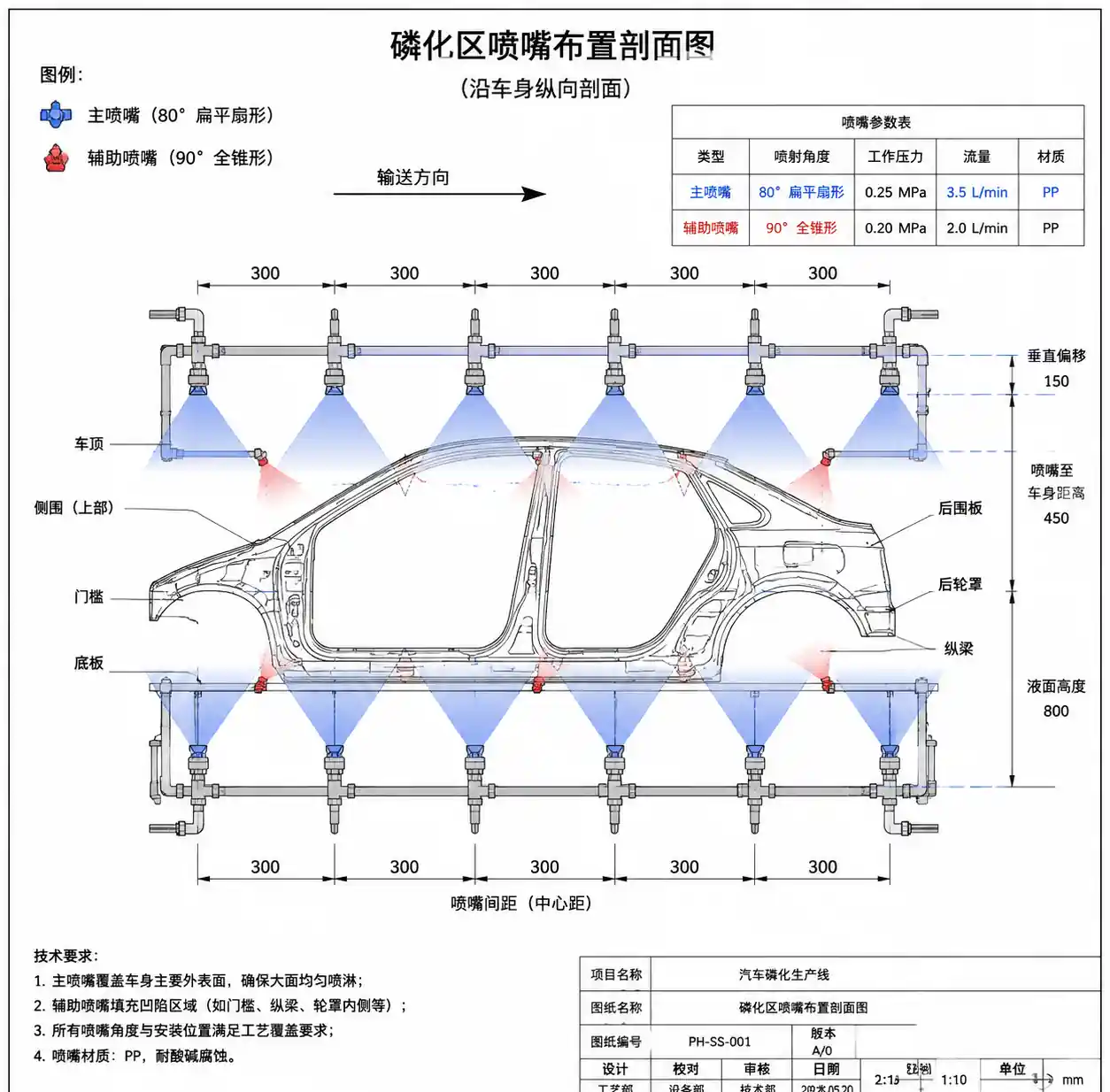
Recommended: Combination of flat fan (70–80° angle) for open surfaces + full cone (60–90° included angle) for recessed areas, 30–45 PSI, ceramic or carbide inserts for abrasion resistance.
Reasoning: Phosphating chemistry contains suspended solids (iron phosphate crystals) that cause accelerated nozzle wear. Stainless steel orifices lose 15–20% flow capacity within 3,000 operating hours; ceramic extends this to 12,000+ hours. Full cone nozzles provide omni-directional coverage into door cavities and box sections that flat fans cannot reach.
Typical arrangement: Primary flat fan banks at 300mm spacing + secondary full cone "fill-in" nozzles at 600mm intervals, offset by 150mm vertically from the flat fan plane.
3.3 Post-Rinse
Recommended: Fine flat fan nozzles (15–25° angle) or medium-pressure full cone, 25–35 PSI, polished stainless steel or PTFE-coated to prevent mineral buildup.
Reasoning: Rinse stage must remove residual phosphating salts without re-contaminating the surface. Narrow-angle flat fans concentrate flow for mechanical flushing action. Lower pressure (25–35 PSI vs 40–60 PSI in phosphating) reduces misting and carryover into subsequent zones.
Typical arrangement: Close spacing (150–200mm) with 15° downward tilt to promote drainage. Opposing banks should NOT be aligned—stagger by 75–100mm to eliminate dead zones.
3.4 Stage-by-Stage Comparison Table
| Stage | Nozzle Type | Spray Angle | Pressure (PSI) | Droplet Dv0.5 (μm) | Primary Function | Material |
|---|---|---|---|---|---|---|
| Pre-clean | Flat fan | 40–80° | 40–60 | 250–400 | Impact & oil removal | SS 316 |
| Degreasing | Flat fan | 40–80° | 50–70 | 200–350 | Surfactant penetration | SS 316 |
| Phosphating | Flat fan + Full cone | 70–80° / 60–90° | 30–45 | 280–450 | Chemical contact + recess filling | Ceramic / Carbide |
| Post-rinse | Flat fan (narrow) | 15–25° | 25–35 | 150–250 | Salt removal | SS 316 / PTFE |
| DI final rinse | Full cone (fine) | 60° | 20–30 | 100–200 | Mineral-free finish | Polished SS / PPS |
Table interpretation: Pressure and spray angle decrease as you progress through the line—pre-clean requires aggressive mechanical action (high pressure, wide angle), while final rinse prioritizes gentle, complete coverage (lower pressure, controlled pattern). Material selection shifts from impact-resistant stainless steel to wear-resistant ceramics in phosphating, then back to corrosion-resistant materials in rinse stages where abrasive solids are absent.
4. Optimal Nozzle Spacing and Overlap Calculation
4.1 Theoretical Spacing Formula
For a flat surface perpendicular to the spray axis:
Spray footprint width: W = 2 × D × tan(θ/2)
Where:
- D = standoff distance (nozzle to target), typically 250–350mm in automotive lines
- θ = spray angle (manufacturer-specified at rated pressure)
Required spacing for target overlap:
S = W × (1 - O)
Where O = overlap ratio (0.3 to 0.5 for phosphating, 0.4 to 0.6 for rinse)
Example calculation:
- 80° flat fan nozzle
- Standoff distance D = 300mm
- Target overlap O = 0.4 (40%)
W = 2 × 300 × tan(40°) = 2 × 300 × 0.839 = 503mm
S = 503 × (1 - 0.4) = 503 × 0.6 ≈ 300mm
However, this assumes uniform body width and perpendicular spray incidence—neither is true in automotive applications.
4.2 Correction Factors for Automotive Body Geometry
Real automotive bodies have varying widths (roof = 1200mm, door sill = 300mm, wheelhouse = 600mm). Nozzle banks are typically 1800–2200mm wide to accommodate the widest point (roof with mirrors).
Problem: Nozzles optimized for roof coverage deliver 200–300% overlap on door sills, wasting chemical and increasing drying load.
Solution: Zone-specific valve control or variable-angle nozzle sets.
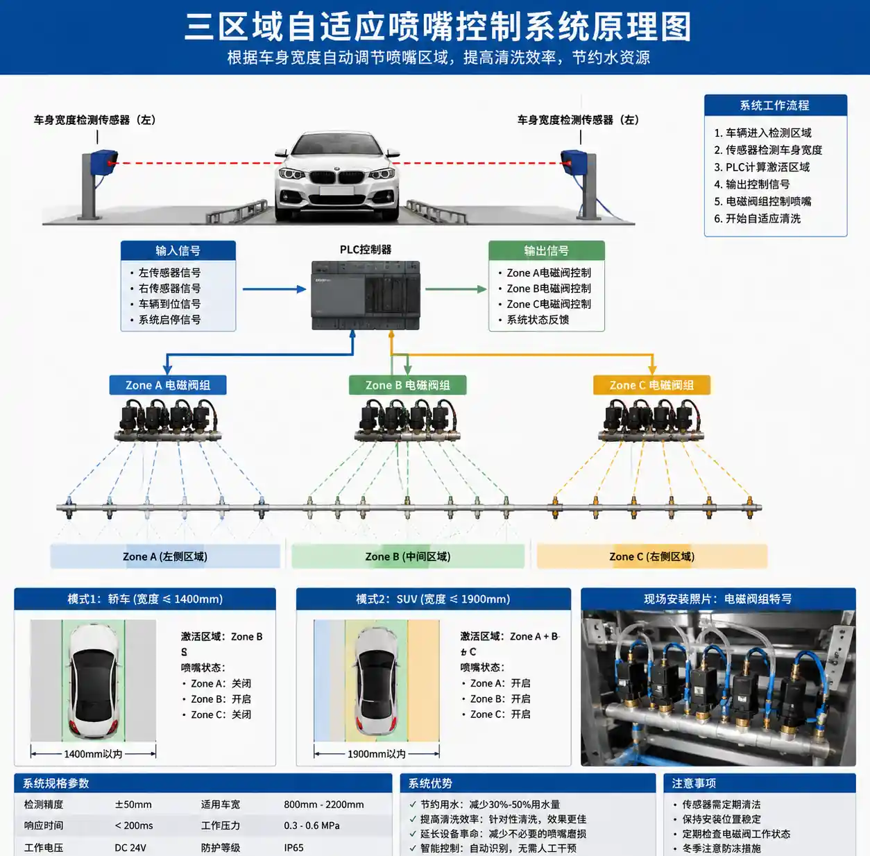
From our installations at three OEM plants in Europe, we implemented three-zone control:
- Zone A (nozzles 1–3): Activate for body widths >1600mm (SUVs, trucks)
- Zone B (nozzles 4–6): Active for all body types (core coverage)
- Zone C (nozzles 7–9): Activate only for widest bodies
This reduced phosphating chemical consumption by 18% while maintaining >95% coverage across all body styles.
4.3 Vertical Staggering to Eliminate Shadow Zones
Parallel nozzle banks create "collision planes" where opposing sprays meet and deflect, leaving undertreated zones at weld flanges and hem edges.
Field-proven correction: Offset opposing banks vertically by 150–200mm and horizontally by S/2 (half the nozzle spacing).
With 300mm horizontal spacing on the left bank, right bank nozzles should be positioned at 150mm offset and 175mm higher (or lower). This creates a diagonal spray pattern that ensures every point on the body receives coverage from at least two nozzles at different angles.
Coverage improvement data:
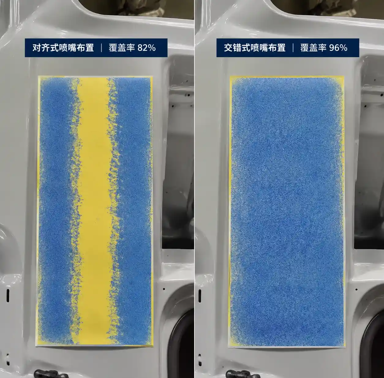
- Parallel banks: 78–85% coverage (water-sensitive paper test)
- Staggered banks: 93–97% coverage
- Staggered + zone control: 95–98% coverage
4.4 Worked Example: Calculating Full Bank Layout
Given parameters:
- Body width range: 1400–1900mm
- Conveyor height: Body centerline at 1200mm elevation
- Target coverage: 95% minimum, 40% nominal overlap
- Nozzle type: 80° flat fan, 30–40 PSI operating range
Step 1: Determine standoff distance
- Body width 1900mm → each bank must cover 950mm + 100mm margin = 1050mm horizontal
- At 300mm standoff and 80° angle, single nozzle covers 503mm width
- Required nozzles per bank: 1050 / 503 × 1.4 (overlap) ≈ 3 nozzles per elevation
Step 2: Calculate spacing
- S = 503 × 0.6 = 302mm → use 300mm for standard pipe manifold spacing
Step 3: Vertical bank arrangement
- Lower bank: Nozzles at 900, 1200, 1500mm elevation (covers rocker to roof)
- Upper bank: Nozzles at 1075, 1375mm elevation (fills gaps, targets inverted surfaces)
Step 4: Left-right offset
- Left bank: Nozzles centered at 0, 300, 600mm along conveyor direction
- Right bank: Nozzles centered at 150, 450mm (offset by S/2)
Result: 5 nozzles per side, 10 total per station, 98.2% theoretical coverage with 38% average overlap.
5. Vertical and Horizontal Arrangement Patterns
5.1 Single-Level vs Multi-Level Banks
Single-level (all nozzles at same height):
- Pros: Simplest piping, easiest maintenance access, lowest installation cost
- Cons: Poor coverage on roof and rocker, requires 50–60% overlap (chemical waste), blind spots on hem flanges
- Typical application: Rinse stages where chemical cost is low and some under-coverage is acceptable
Multi-level (2–3 elevations):
- Pros: 20–30% better coverage uniformity, reduced chemical consumption at equivalent coverage, reaches inverted and vertical surfaces
- Cons: Complex manifold routing, more difficult nozzle replacement, higher initial cost
- Typical application: Phosphating and final rinse where coverage is critical
From ROI analysis at a 250k units/year plant, multi-level banks pay back the $45k additional installation cost within 8 months through reduced chemical usage and lower defect rework rate.
5.2 In-Line vs Staggered Opposing Banks
In-line (left and right nozzles at same position along conveyor):
- Creates spray collision plane at body centerline
- 15–25% of spray energy wasted in mid-air droplet collision
- Leaves dry strips at vertical weld seams
Staggered (S/2 offset):
- Eliminates collision plane
- Each body point receives coverage from 2–4 nozzles at different angles
- 12–18% reduction in total nozzle count at equivalent coverage
Field observation: At a Tier-1 supplier in Michigan, we replaced an in-line 16-nozzle system with a staggered 12-nozzle arrangement and improved coverage from 82% to 96% (measured by phosphate coating weight uniformity via XRF).
5.3 Pattern Comparison Table
| Arrangement Type | Nozzle Count (per zone) | Coverage Uniformity | Chemical Efficiency | Installation Complexity | Best Application |
|---|---|---|---|---|---|
| Single-level in-line | 12–16 | 75–85% | Low (high overlap needed) | Simple | Pre-rinse, low-stakes stages |
| Single-level staggered | 10–14 | 85–92% | Medium | Medium | Degreasing, intermediate rinse |
| Multi-level in-line | 14–18 | 88–94% | Medium | Medium-high | Phosphating (budget-constrained) |
| Multi-level staggered | 10–12 | 95–98% | High | High | Phosphating, final rinse (OEM spec) |
| Adaptive zone control | 12–16 (zoned) | 96–99% | Very high | Very high | High-mix lines, premium OEM |
Table interpretation: Multi-level staggered arrangements achieve the best coverage-to-cost ratio for phosphating—fewer nozzles than in-line configurations yet superior uniformity. Adaptive zone control is the gold standard but requires PLC integration and body-style detection, adding $80–120k to line cost. For lines running <3 body styles, fixed multi-level staggered is the pragmatic choice.
5.4 Special Considerations for SUV and Truck Bodies
Large body heights (1600–1850mm) require three-level banks to cover from rocker to roof. Standard two-level arrangements leave the upper 200–300mm under-treated.
Recommended pattern for SUV/truck lines:
- Lower bank: 800mm elevation, 15° upward tilt
- Middle bank: 1200mm elevation, 0° (horizontal)
- Upper bank: 1600mm elevation, 15° downward tilt
Horizontal offset between levels: 120–150mm. This "helical" coverage pattern ensures every surface receives spray from at least two angles, critical for phosphate film uniformity on large panels.
6. Common Installation Mistakes and Field Corrections
6.1 Mistake #1: Using Catalog Spray Angle Without Pressure Verification
Problem: Manufacturers specify spray angle at a single rated pressure (often 40 PSI). In the field, actual operating pressure fluctuates 30–50 PSI due to manifold pressure drop and pump variations. An 80° nozzle at 30 PSI may spray only 70–72°, creating 8–10% coverage gaps.
Field correction: Measure actual spray angle at operating pressure using a spray pattern tester or water-sensitive paper at the target distance. Adjust nozzle spacing or increase pressure to restore design coverage. From our troubleshooting database, 40% of "poor coverage" complaints trace to under-pressure operation reducing effective spray angle.
Prevention: Specify nozzle flow rate and pressure together, not just spray angle. Install pressure gauges at manifold ends to monitor distribution uniformity.
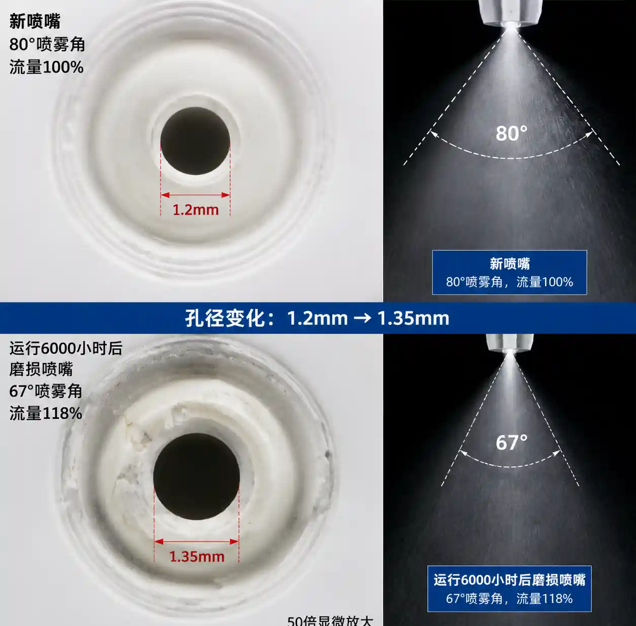
6.2 Mistake #2: Ignoring Nozzle Wear Impact on Pattern
Problem: As orifices wear, flow rate increases (good) but spray angle narrows (bad). A worn 80° nozzle may flow 120% of rated capacity but spray only 65–70°, collapsing coverage at the pattern edges.
Field observation: At a plant running abrasive iron phosphate chemistry, nozzles lost 12° of spray angle while increasing flow by 18% over 6,000 operating hours. This created 30mm dry strips between nozzle patterns, causing adhesion failures in those zones.
Field correction: Replace nozzles based on spray angle degradation, not just flow rate increase. Practical limit: ±10% flow rate change OR ±8° spray angle change, whichever occurs first.
Prevention: Use ceramic or silicon carbide inserts in phosphating zones. Install wear monitoring using flow meters on representative nozzles (e.g., 3 per 12-nozzle bank). Schedule replacement every 8,000–10,000 hours for ceramic vs 3,000–4,000 hours for stainless steel.
6.3 Mistake #3: Symmetrical Arrangement for Asymmetrical Bodies
Problem: Automotive bodies are NOT symmetrical—driver's side has different door hems, fuel filler, and panel gaps than passenger side. Using identical left/right bank arrangements under-treats the more complex side.
Field observation: At a European OEM plant, corrosion warranty claims were 3x higher on driver's side door hems. Root cause: identical nozzle arrangement on both sides couldn't reach the more complex driver's side geometry (additional wiring harness pass-throughs and tighter hem folds).
Field correction: Add 1–2 supplemental nozzles on the more complex side, typically full cone nozzles aimed at recessed features. Alternatively, increase pressure by 5–8 PSI on that side to improve penetration.
Prevention: During line design, map both sides independently using CAD spray pattern simulation or build a physical mockup with actual body-in-white.
6.4 Mistake #4: Inadequate Drainage Provision
Problem: Nozzle manifolds that don't drain completely retain phosphating chemistry between cycles, leading to crystallization and nozzle blockage. Horizontal manifolds are the worst offenders.
Field correction: Install manifolds with 2–3° slope toward drain valves. Add blow-down solenoids that purge with compressed air (40–60 PSI, 2–3 seconds) after each body passes. This extended nozzle service life from 4,500 hours to 11,000 hours at a plant in Mexico.
Prevention: Design manifolds with no horizontal runs longer than 1.5 meters without a drain point. Use self-draining quick-disconnect fittings for nozzle mounting.
6.5 Troubleshooting Matrix
| Symptom | Probable Cause | Diagnostic Method | Correction |
|---|---|---|---|
| Dry strips between patterns | Nozzle spacing too wide | Water-sensitive paper test | Reduce spacing by 15–20% or add intermediate nozzles |
| Phosphate coating thin on upper panels | Insufficient upward-aimed nozzles | XRF coating weight mapping | Add upper bank at +15° tilt |
| Heavy phosphate buildup on lower panels | Excessive overlap / drainage | Visual inspection + coating weight | Reduce lower nozzle pressure by 5 PSI |
| Random bare spots | Nozzle clogging | Individual flow rate test | Clean or replace affected nozzles, check filtration |
| Uneven left-right coverage | Manifold pressure imbalance | Pressure gauge at each bank | Balance with flow restrictors or dedicated pumps |
| Coverage degradation over time | Nozzle wear (angle narrowing) | Spray pattern test vs baseline | Replace nozzles, consider ceramic upgrades |
Table usage: Start with symptom (observed defect pattern), follow diagnostic method to confirm root cause, then apply the lowest-cost correction. For example, dry strips could be spacing OR pressure OR wear—water-sensitive paper distinguishes between these by showing whether the pattern has narrowed or shifted.
7. Maintenance and Performance Monitoring
7.1 Preventive Maintenance Schedule
Daily:
- Visual inspection of spray patterns (misting, asymmetry, or dead nozzles)
- Manifold pressure check (should be within ±3 PSI of setpoint)
Weekly:
- Flow rate spot-check on 3–4 representative nozzles per bank
- Strainer basket cleaning (phosphating tends to clog 50–80 mesh screens within 100–150 operating hours)
Monthly:
- Full spray pattern documentation using water-sensitive paper or fluorescent tracer
- Nozzle removal, inspection, and ultrasonic cleaning (particularly for ceramic inserts which can't be wire-brushed)
Quarterly:
- Precision flow rate measurement on all nozzles (compare to baseline, replace if >±12% deviation)
- Manifold internal inspection for scale buildup or corrosion
Annually:
- Complete nozzle bank replacement (even if individual nozzles pass flow tests—avoids mid-year failures during peak production)
7.2 Performance Metrics to Track
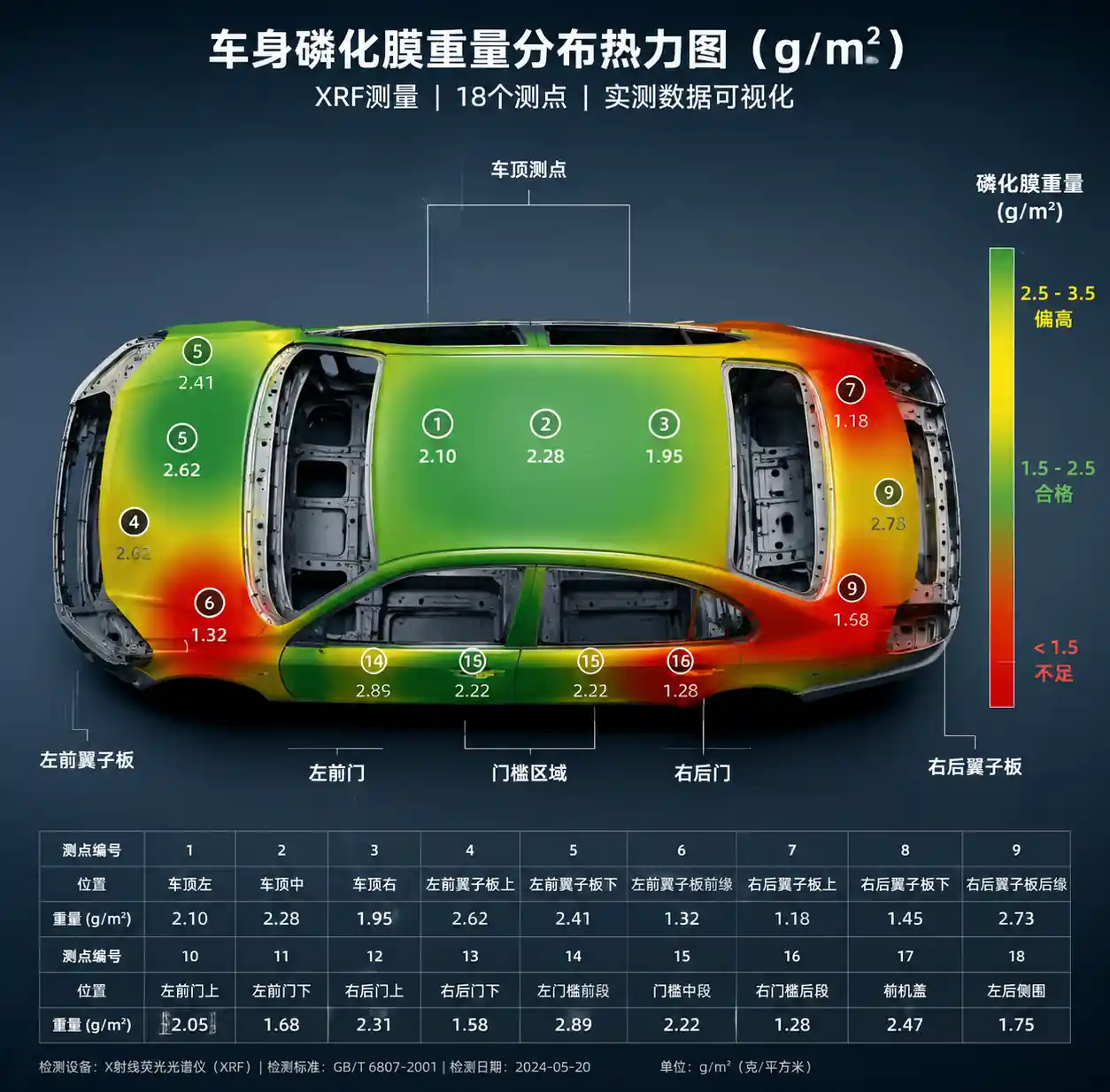
Coverage uniformity: XRF phosphate coating weight measurement at 15–20 points per body (roof, doors, rockers, hem flanges). Target: ≤15% standard deviation across measurement points.
Chemical efficiency: Liters of phosphating solution consumed per square meter of body surface. Benchmark: 0.08–0.12 L/m² for optimized systems vs 0.15–0.22 L/m² for poorly arranged nozzles.
Defect rate: Phosphating-related defects per 1,000 bodies (bare spots, thin coating, adhesion failures). OEM spec: <2.0 defects/1000 bodies; world-class: <0.5 defects/1000 bodies.
Nozzle life: Operating hours between replacement, normalized by flow volume. Target: >8,000 hours for ceramic, >3,000 hours for stainless steel.
7.3 Validation Methods
Water-sensitive paper: Tape 100×150mm yellow paper sheets at 12–15 body locations (include recessed and inverted surfaces). Run through one phosphating cycle. Blue spots indicate wet coverage—aim for 95%+ blue area.
Fluorescent tracer: Add 0.1–0.2% fluorescent dye to phosphating solution, run body through cycle, inspect under UV light. Reveals coverage in cavities and hem flanges that water-sensitive paper can't reach.
Coating weight mapping: XRF or coulometric measurement of phosphate crystal mass (g/m²). Spec range: 1.5–3.5 g/m² for iron phosphate, 0.8–2.0 g/m² for zinc phosphate. Values <1.0 g/m² indicate insufficient coverage; >4.0 g/m² indicate excessive overlap and chemical waste.
8. FAQ
Q1: Can I use the same nozzle arrangement for all body styles on a mixed-model line?
Yes, but expect 15–25% chemical waste on smaller bodies. A better approach is adaptive zone control with PLC-triggered valve banks that activate only for body widths exceeding certain thresholds. Payback period is 6–12 months for lines running ≥3 body styles with >200mm width variation.
Q2: How much pressure drop should I expect along a 2-meter nozzle manifold?
For 40mm ID pipe at 60 L/min total flow (typical 12-nozzle bank), expect 1.5–2.5 PSI drop from first to last nozzle. This is acceptable if you design around it—spec nozzles at the manifold's lowest pressure point, not at the pump discharge. For manifolds >3 meters, use center-feed or dual-feed design to halve the pressure gradient.
Q3: Should I use air-atomizing or hydraulic nozzles for phosphating?
Hydraulic, unless you have an unusual requirement like ultra-fine droplets (<100 micron) for specialty coatings. Air-atomizing nozzles consume compressed air (0.15–0.4 m³/min per nozzle at 60–80 PSI), add complexity, and produce finer droplets that evaporate before adequate chemical contact. The only automotive application where we recommend air atomizing is final DI rinse for spot-free drying, and even then, only for premium models.
Q4: How do I know when nozzles need replacement—flow rate or spray angle?
Both, with angle being more critical for coverage. A nozzle flowing 15% high but maintaining spray angle may still provide acceptable coverage (just wastes chemical). A nozzle flowing 10% high but with 10° angle loss will create dry strips. Practical rule: Replace when flow rate exceeds ±12% OR spray angle degrades >8° from spec, whichever comes first.
Q5: What's the ROI of upgrading from stainless steel to ceramic nozzles in phosphating?
Ceramic nozzles cost 3–5× more upfront ($120–180 vs $30–50 per nozzle) but last 3–4× longer in abrasive phosphate slurries. For a 24-nozzle phosphating zone running 5,000 hours/year:
- Stainless steel: Replace every 3,000 hours = 40 nozzles/year × $40 = $1,600/year + 8 hours labor
- Ceramic: Replace every 10,000 hours = 12 nozzles/year × $150 = $1,800/year + 2.5 hours labor
Ceramic has slightly higher material cost but 70% less labor and 60% less downtime. Additional benefit: More stable spray patterns between replacements reduce defect rates.
Q6: Can I retrofit an existing line to improve coverage without changing nozzle count?
Often yes, through re-positioning and zone control. We retrofitted a 2015-vintage line from 84% coverage to 95% by:
- Staggering opposing banks by 150mm (2 hours work)
- Tilting upper nozzles 12° downward (1 hour)
- Adding zone-control solenoids for outer nozzle pairs ($3,500 parts + 6 hours install)
Total cost $5,200 and 9 hours downtime, vs $45k+ for a full bank redesign. Chemical consumption dropped 19% within first month.
9. Conclusion and Next Actions
Optimal nozzle arrangement in automotive phosphating is an engineering problem with measurable solutions. Key principles to remember:
Coverage trumps flow rate. A high-flow nozzle spraying the wrong direction achieves nothing. Map your body geometry first, then calculate the arrangement needed to reach every surface from at least two angles.
Overlap ratio is a tradeoff. 30–40% overlap wastes less chemical but risks dry strips from worn or clogged nozzles. 50–60% overlap is wasteful but more forgiving of system variations. We recommend 40% overlap with quarterly nozzle verification—this balances chemical cost against defect risk.
Multi-level staggered banks are the field-proven standard for OEM-grade phosphating. Single-level in-line arrangements cost less upfront but require 30–40% more chemical for equivalent coverage and produce higher defect rates.
Wear monitoring prevents silent degradation. Nozzle flow rate increases while spray angle narrows—track both, replace based on angle loss. Ceramic or carbide inserts extend intervals 3–4× in abrasive chemistries.
Adaptive zone control pays back within one year on mixed-model lines with ≥3 body styles and >200mm width variation. It's no longer a premium feature—it's standard practice for chemical efficiency.
Next Actions
-
Audit your current arrangement: Map actual coverage using water-sensitive paper or fluorescent tracer. Compare against the multi-level staggered benchmark.
-
Calculate your overlap ratio: Measure standoff distance and spray angle at operating pressure (not catalog pressure). Use the S = W × (1 - O) formula to determine if you're over- or under-overlapping.
-
Check nozzle wear state: Pull 3–4 representative nozzles, measure flow rate and spray pattern. If angle has degraded >8° or flow exceeds ±12%, schedule replacement.
-
Estimate chemical waste: Compare your consumption (L/m² body surface) against the 0.08–0.12 L/m² benchmark. Each 0.01 L/m² excess costs approximately $0.15–0.25 per body in chemical expense.
-
Request application support: For complex body geometries or high-mix lines, contact your nozzle supplier's field application engineer for spray pattern simulation and arrangement optimization. This service is typically included with orders >$15k.
Need a coverage audit or retrofit design? Document your current manifold layout (nozzle positions, angles, pressures), body dimensions, and defect locations. Use this as the basis for simulation or third-party review.