


Inconsistent Coating Thickness? How to Diagnose the Link Between Pressure Fluctuations and Nozzle Wear
Purpose: This guide walks you through a systematic approach to identifying and resolving coating thickness inconsistencies caused by pressure instability and nozzle wear—two of the most common yet frequently misdiagnosed issues in spray coating operations.
Table of Contents
- 1. 1. Introduction: Why Coating Thickness Varies and What It Costs You
- 2. 2. Understanding the Flow-Pressure-Wear Triangle
- 2.1. 2.1 The Square Root Law of Hydraulic Nozzles
- 2.2. 2.2 How Nozzle Wear Changes the Flow Coefficient K
- 2.3. 2.3 Why Pressure and Wear Interact
- 3. 3. Pressure Fluctuation: Root Causes and Detection Methods
- 3.1. 3.1 Common Causes of Pressure Instability
- 3.2. 3.2 Detection and Measurement Protocol
- 3.3. 3.3 Quick Field Test
- 4. 4. Nozzle Wear: How Orifice Enlargement Changes Everything
- 4.1. 4.1 Mechanisms of Nozzle Wear
- 4.2. 4.2 How Wear Manifests in Coating Performance
- 4.3. 4.3 Field Data: Wear Rates by Nozzle Material
- 5. 5. Diagnostic Protocol: Isolating Pressure vs. Wear Issues
- 5.1. 5.1 Baseline Flow Test (New Nozzle)
- 5.2. 5.2 In-Service Flow Test (Suspect Nozzle)
- 5.3. 5.3 Pressure Variation Test
- 5.4. 5.4 Spray Pattern Evaluation
- 5.5. 5.5 Decision Matrix
- 6. 6. Material Selection and Wear Life Economics
- 6.1. 6.1 Total Cost of Ownership (TCO) Calculation
- 6.2. 6.2 When to Choose Lower-Cost Materials
- 7. 7. Preventive Maintenance Schedule and Acceptance Criteria
- 7.1. 7.1 Recommended Inspection Intervals
- 7.2. 7.2 Documentation and Traceability
- 7.3. 7.3 Acceptance Criteria for Continued Use
- 8. 8. FAQ
- 8.1. Q1: Can I just increase pressure to compensate for a worn nozzle?
- 8.2. Q2: How do I know if my pressure fluctuation is "normal"?
- 8.3. Q3: My nozzles wear out in 100 hours, but the manufacturer says they should last 500 hours. Why?
- 8.4. Q4: Is there a way to refurbish worn nozzles?
- 8.5. Q5: How do I choose between tungsten carbide and silicon carbide?
- 8.6. Q6: Can nozzle wear cause safety issues?
- 9. 9. Conclusion and Next Steps
1. Introduction: Why Coating Thickness Varies and What It Costs You
Coating thickness inconsistency is one of the most reported quality issues in roll coating, spray booth, and web coating operations. When dry film thickness deviates by more than ±10% from target, you face increased rework rates, coating material waste, and potential product rejection. In automotive clear coat lines, for example, a 15-micron variance can mean the difference between pass and fail on gloss measurements.
In our field experience across dozens of coating facilities, we have traced roughly 60% of unexplained thickness variation to two interrelated factors: supply pressure fluctuations and progressive nozzle wear. These issues often appear together because worn nozzles mask pressure problems, and unstable pressure accelerates wear.
This guide provides a step-by-step diagnostic framework to:
- Distinguish between pressure-driven and wear-driven thickness variation
- Quantify the economic impact of delaying nozzle replacement
- Establish predictive maintenance intervals based on your coating media properties
- Select nozzle materials that minimize total cost of ownership in abrasive or corrosive fluids
By the end, you will have a replicable protocol to troubleshoot coating inconsistencies and make data-backed decisions on nozzle replacement timing.
2. Understanding the Flow-Pressure-Wear Triangle
Before jumping into diagnostics, it is critical to understand the fundamental relationship between flow rate, pressure, and nozzle wear. Many operators assume that a 20% pressure drop means a 20% flow reduction—this is incorrect and leads to misdiagnosis.
2.1 The Square Root Law of Hydraulic Nozzles
For hydraulic (non-air-assisted) nozzles, flow rate Q is governed by:
Q = K × √P
Where:
- Q = flow rate (liters per minute or gallons per minute)
- K = nozzle flow coefficient (a constant for a given orifice size and geometry)
- P = supply pressure (bar or PSI)
Key insight: If pressure drops from 40 PSI to 30 PSI (a 25% drop), flow only decreases by √(30/40) ≈ 0.866, or about 13.4%. Conversely, if you try to compensate for a worn nozzle by increasing pressure from 40 to 60 PSI, flow only increases by √(60/40) ≈ 1.225, or 22.5%—not the 50% increase you might expect.
2.2 How Nozzle Wear Changes the Flow Coefficient K
When the nozzle orifice erodes or enlarges due to abrasive wear, the flow coefficient K increases. A 10% increase in orifice diameter typically results in roughly a 20% increase in flow rate at the same pressure, because flow area scales with the square of the diameter.
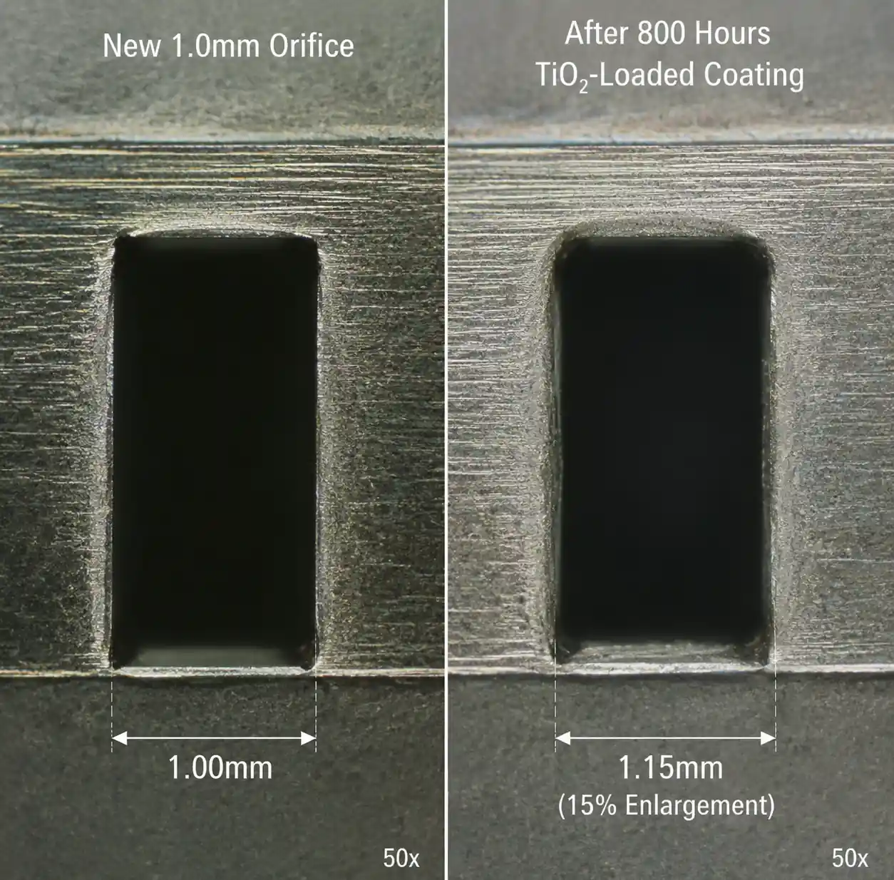
Example from the field:
We measured a flat fan nozzle in a waterborne coating line after 800 hours of operation spraying a TiO₂-loaded basecoat. The orifice diameter increased from 1.0 mm to 1.15 mm (15% enlargement). At 30 PSI, flow jumped from 0.85 LPM to 1.18 LPM—a 39% increase. The operator had been compensating by reducing pressure to 20 PSI, which brought flow back down to 0.96 LPM, but this also narrowed the spray angle from 80° to about 65°, causing stripe defects at the web edges.
2.3 Why Pressure and Wear Interact
Worn nozzles are more sensitive to pressure variation because the larger orifice offers less flow resistance. A ±2 PSI pressure swing that causes ±7% flow variation in a new nozzle can cause ±10% variation in a worn nozzle with 20% orifice enlargement. Additionally, higher velocities through the enlarged orifice can accelerate erosion in a feedback loop.
3. Pressure Fluctuation: Root Causes and Detection Methods
3.1 Common Causes of Pressure Instability
From our diagnostic work in coating facilities, the most frequent causes are:
- Pump cavitation or air entrainment – Particularly in recirculating systems where return flow introduces bubbles. Symptoms include erratic pressure gauge needle movement and audible pump noise.
- Undersized or clogged supply filters – A 100-mesh filter loaded with dried coating particles can cause 5–15 PSI pressure drop, and the drop increases as the filter loads during a shift.
- Pressure regulator hysteresis – Low-cost spring-loaded regulators can have ±3 PSI hysteresis; electronic regulators reduce this to ±0.2 PSI.
- Shared supply manifold with poor flow balancing – If multiple spray zones draw from one manifold without individual pressure compensation, flow demand spikes in one zone will rob pressure from others.
- Temperature-driven viscosity changes – A 10°C temperature rise can reduce coating viscosity by 20–40%, changing flow characteristics and effective system pressure.
3.2 Detection and Measurement Protocol
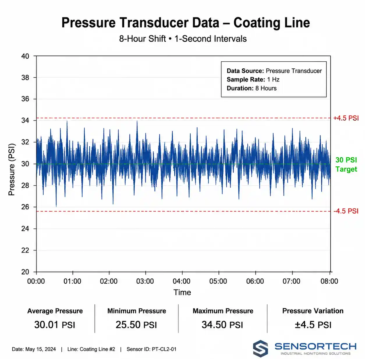
Step 1: Install a high-resolution pressure transducer (0.1 PSI resolution minimum) at the nozzle inlet or as close as possible. Do not rely solely on a gauge at the pump—line losses can be significant.
Step 2: Log pressure continuously over a full production shift at 1-second intervals (or faster if you suspect rapid fluctuations). Many operators only check pressure at startup, missing mid-shift drift.
Step 3: Calculate pressure statistics:
- Mean pressure
- Standard deviation
- Min/max range
- Coefficient of variation (CV = standard deviation / mean)
Acceptance criteria:
For coating operations requiring ±5% thickness control, pressure CV should be below 2%. For ±10% thickness tolerance, CV below 5% is acceptable.
Step 4: Cross-correlate pressure log with coating thickness measurements. If thickness variation tracks pressure variation with a time lag (accounting for web travel time), pressure is the dominant factor.
3.3 Quick Field Test
If you lack logging equipment, perform this manual test:
- Set target pressure (e.g., 30 PSI) and record nozzle flow rate by collecting spray into a graduated cylinder for 30 seconds.
- Artificially vary pressure ±10% (27 PSI and 33 PSI) and re-measure flow.
- Compare measured flow change to theoretical √P relationship. If measured change significantly exceeds theory, suspect air entrainment or two-phase flow.
4. Nozzle Wear: How Orifice Enlargement Changes Everything
4.1 Mechanisms of Nozzle Wear
Nozzle orifice wear occurs through three primary mechanisms:
- Erosive wear: Hard particles (TiO₂, silica, metallic pigments) impact the orifice edge at high velocity, mechanically removing material. Wear rate scales with particle hardness, concentration, and velocity (roughly proportional to pressure).
- Corrosive wear: Acidic or alkaline coatings chemically attack the nozzle material, especially at elevated temperatures.
- Cavitation erosion: Vapor bubble collapse near sharp edges (common at very high pressures or with low-viscosity solvents) causes localized pitting.
In waterborne coatings with 15–25% pigment loading, erosive wear dominates. In aggressive chemical applications (e.g., pickling or etching sprays), corrosion is the main driver.
4.2 How Wear Manifests in Coating Performance
As the orifice enlarges, you will see:
- Increased flow rate at constant pressure – This directly increases wet film thickness.
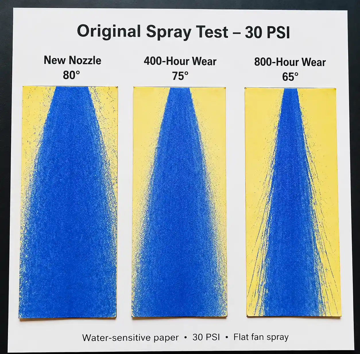
- Spray angle widening or narrowing – Depends on nozzle type; flat fans often narrow as the orifice becomes less sharp, while full cones may widen.
- Droplet size distribution shift – Larger orifices generally produce coarser droplets, reducing atomization quality and increasing orange peel or sag defects in vertical coating.
- Spray pattern distortion – Asymmetric wear creates uneven spray distribution, visible as streaks or stripe defects.
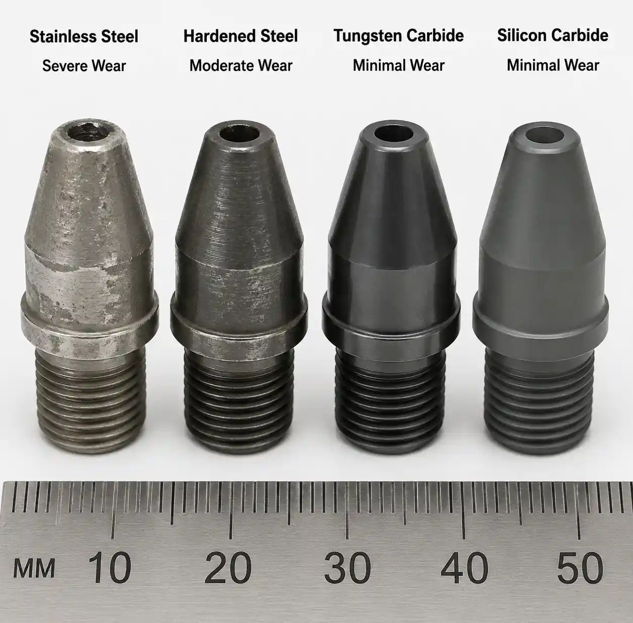
4.3 Field Data: Wear Rates by Nozzle Material
The table below summarizes relative wear life from our accelerated slurry testing (20% alumina, 3000 PSI, 500 hours) and field validations in coating lines:
| Nozzle Material | Mohs Hardness | Relative Wear Life | Cost Multiplier | Best Use Case |
|---|---|---|---|---|
| 303 Stainless Steel | ~5.5 | 1x (baseline) | 1x | Non-abrasive, water-based, low budget |
| Hardened 17-4 PH Steel | ~6.5 | 2–3x | 1.5x | Moderate abrasives, short replacement cycles |
| Tungsten Carbide | ~9 | 15–25x | 8–12x | Highly abrasive slurries, long production runs |
| Silicon Carbide Ceramic | ~9.5 | 20–30x | 6–10x | Abrasive + corrosive, but brittle—avoid pressure spikes >70 PSI |
| Alumina Ceramic (99.5%) | ~9 | 10–20x | 4–6x | Moderate abrasives, cost-sensitive, avoid thermal shock |
Economic breakeven example:
Assume a stainless steel nozzle costs $15 and lasts 200 hours in your coating. A tungsten carbide nozzle costs $120 (8x) but lasts 4,000 hours (20x). Cost per hour: stainless = $0.075/hr, carbide = $0.03/hr. Carbide reduces cost by 60%, plus you avoid 19 change-outs and their associated downtime.
However, if your runs are short (seasonal color changes every 100 hours), the carbide nozzle never pays back—stick with hardened steel or alumina.
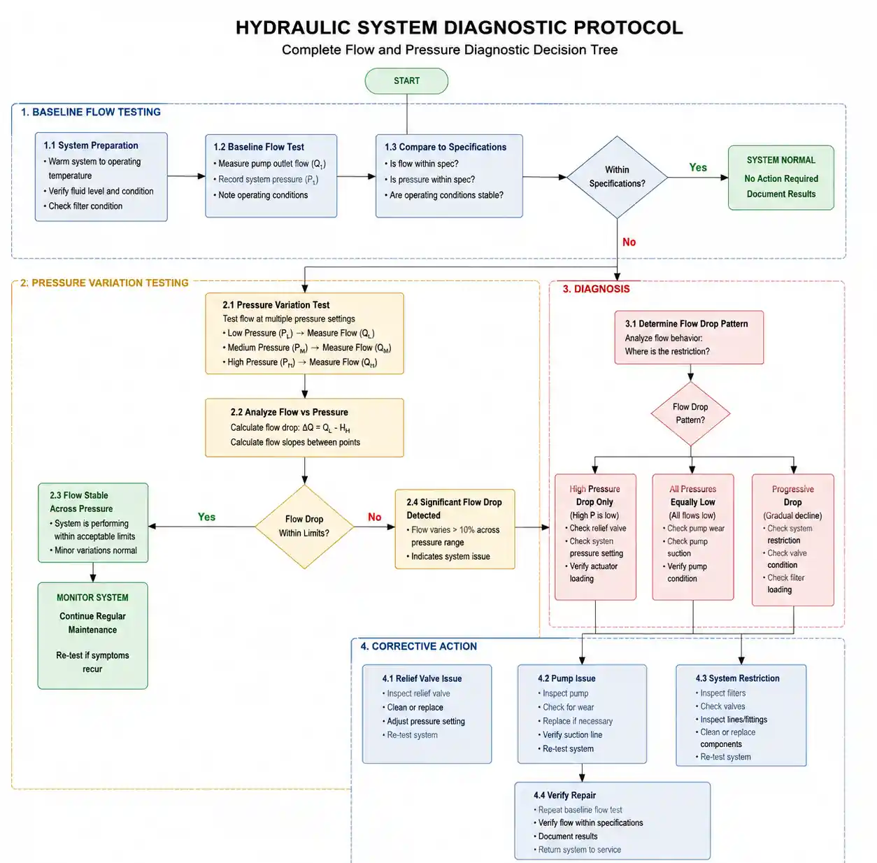
5. Diagnostic Protocol: Isolating Pressure vs. Wear Issues
This is the core troubleshooting sequence. Execute it methodically to avoid chasing ghosts.
5.1 Baseline Flow Test (New Nozzle)
Objective: Establish a reference flow rate at your operating pressure with a known-good nozzle.
Procedure:
- Install a new nozzle of the correct spec (verify orifice size with pin gauges if available).
- Set system pressure to your target setpoint (e.g., 30 PSI) using the pressure transducer at the nozzle inlet.
- Collect spray output into a container for exactly 60 seconds (use a stopwatch). Measure volume in mL or ounces.
- Calculate flow rate Q₀ in LPM or GPM.
- Record spray pattern on water-sensitive paper or a test panel—photograph it for later comparison.
Data to log:
- Nozzle part number, serial number (if applicable), installation date
- Measured flow Q₀ at pressure P₀
- Spray angle (measure with protractor if possible)
- Pattern quality (uniform, streaky, etc.)
5.2 In-Service Flow Test (Suspect Nozzle)
Repeat the flow test procedure above with the nozzle currently in service. Compare Q_current to Q₀.
Interpretation:
- Q_current / Q₀ < 0.95: Possible partial clogging (inspect nozzle, check filter condition).
- 0.95 ≤ Q_current / Q₀ ≤ 1.10: Nozzle is within acceptable wear tolerance.
- Q_current / Q₀ > 1.10: Significant wear suspected—proceed to Step 5.3.
- Q_current / Q₀ > 1.25: Severe wear—immediate replacement recommended.
Note on clogging vs. wear: If flow is lower than baseline, remove the nozzle and inspect the orifice under magnification. Clogging shows buildup or fibers; wear shows smooth, enlarged geometry.
5.3 Pressure Variation Test
Objective: Determine if pressure instability alone can explain thickness variation.
Procedure:
- With the suspect nozzle still installed, log pressure continuously for 30 minutes during normal coating operation.
- Simultaneously measure coating thickness at 10 evenly spaced points across the web width every 5 minutes (60 data points total).
- Calculate correlation coefficient between pressure and thickness.
Interpretation:
- Correlation > 0.7: Pressure variation is a primary driver—focus on stabilizing supply pressure (check pump, regulator, filter).
- Correlation < 0.4: Thickness variation is likely due to nozzle wear or pattern distortion—pressure is stable enough.
- 0.4 < Correlation < 0.7: Both factors contribute—address pressure first (cheaper and faster), then reassess nozzle.
5.4 Spray Pattern Evaluation
Visual inspection reveals issues that flow rate alone cannot:
- Spray the nozzle onto water-sensitive paper at the design standoff distance for 2 seconds.
- Compare to the baseline pattern from Step 5.1.
- Look for:
- Asymmetry or "tailing" – Indicates uneven orifice wear or internal vane damage.
- Narrowing spray angle – Common in worn flat fan nozzles; reduces edge coverage.
- Coarse droplets or "spitting" – Enlarged orifice reduces atomization energy.
Acceptance criteria:
If spray angle has changed by more than ±5° or pattern shows visible streaks, replace the nozzle regardless of flow rate test results. Pattern defects directly cause coating defects that may not show up in average thickness measurements.
5.5 Decision Matrix
| Flow Increase | Pressure CV | Pattern Quality | Diagnosis | Action |
|---|---|---|---|---|
| <10% | <2% | Good | Normal operation | Continue monitoring |
| <10% | >5% | Good | Pressure instability | Fix pump/regulator/filter |
| >15% | <2% | Distorted | Advanced nozzle wear | Replace nozzle immediately |
| >15% | >5% | Distorted | Both pressure and wear issues | Stabilize pressure, then replace nozzle |
| >25% | Any | Any | Severe wear | Emergency nozzle replacement, check for root cause of accelerated wear |
6. Material Selection and Wear Life Economics
Choosing the right nozzle material is an economic optimization problem, not just a performance question.
6.1 Total Cost of Ownership (TCO) Calculation
TCO includes:
- Initial nozzle cost – Purchase price per unit
- Replacement labor cost – Downtime + technician time (often $50–150 per change-out)
- Coating waste during startup – Off-spec production during flow stabilization after nozzle change
- Quality loss risk – Defects from worn nozzles that slip past inspection
Example calculation:
Assume a coating line runs 6,000 hours per year. Downtime cost is $200/hour. Labor for nozzle change is 0.5 hours at $80/hour.
| Material | Nozzle Cost | Life (hrs) | Changes/yr | Labor/yr | Downtime/yr | Nozzle Cost/yr | Total TCO/yr |
|---|---|---|---|---|---|---|---|
| Stainless | $15 | 300 | 20 | $800 | $2,000 | $300 | $3,100 |
| Hardened Steel | $25 | 750 | 8 | $320 | $800 | $200 | $1,320 |
| Tungsten Carbide | $120 | 5,000 | 1.2 | $48 | $120 | $144 | $312 |
Result: Tungsten carbide reduces TCO by 90% despite being 8x more expensive per unit. The breakeven occurs after just 1,500 hours of operation.
6.2 When to Choose Lower-Cost Materials
Carbide is not always optimal:
- Short campaign lengths: If you change colors or formulations every 200 hours, the nozzle never reaches its wear life—use hardened steel.
- Risk of mechanical damage: In automated systems with frequent nozzle contact or high-vibration environments, brittle ceramics can crack—stainless may be safer.
- Budget constraints in multi-nozzle arrays: A 50-nozzle spray bar requiring $6,000 upfront for carbide vs. $750 for stainless may exceed CapEx approval—consider staged upgrades on the highest-wear positions first.
7. Preventive Maintenance Schedule and Acceptance Criteria
Reactive nozzle replacement (waiting for visible defects) is costly. Shift to predictive maintenance.
7.1 Recommended Inspection Intervals
| Coating Type | Inspection Frequency | Flow Test Frequency | Replacement Trigger |
|---|---|---|---|
| Water-based, low solids | Every 500 hours | Every 1,000 hours | Flow increase >15% |
| Solvent-based, moderate solids | Every 300 hours | Every 600 hours | Flow increase >12% |
| High-solids, abrasive (TiO₂, metal flake) | Every 200 hours | Every 400 hours | Flow increase >10% or pattern distortion |
| Corrosive or high-temperature | Every 250 hours | Every 500 hours | Visible corrosion or flow increase >12% |
Inspection procedure:
- Visual inspection for cracks, corrosion, or buildup.
- Flow rate test at standard pressure (compare to baseline Q₀).
- Spray pattern test on water-sensitive paper.
7.2 Documentation and Traceability
Maintain a nozzle logbook (digital or paper) with:
- Nozzle ID (position in the spray bar, e.g., "Zone 2, Nozzle 5")
- Installation date and hour meter reading
- Baseline flow rate Q₀ at installation
- Inspection results (date, flow rate, pattern quality)
- Removal date and total hours in service
- Reason for removal (scheduled replacement, premature failure, campaign end)
This data allows you to calculate actual wear rates for your specific coating chemistry and refine replacement intervals.
7.3 Acceptance Criteria for Continued Use
Do not continue operating a nozzle if:
- Flow rate has increased by >15% from baseline (>10% for critical applications)
- Spray angle has changed by >±5°
- Visible pattern distortion (streaks, tailing, or asymmetry)
- Any cracks or corrosion visible under 10x magnification
- Coating thickness variation exceeds process capability limits
Even if the nozzle "still works," operating outside these limits increases scrap rate and risks catastrophic pattern failure mid-production.
8. FAQ
Q1: Can I just increase pressure to compensate for a worn nozzle?
No. While increasing pressure does reduce flow somewhat (remember, Q ∝ √P, not Q ∝ P), it also changes spray angle, droplet size, and impact force. You are masking the symptom, not fixing the root cause. Plus, higher pressure accelerates further wear.
Q2: How do I know if my pressure fluctuation is "normal"?
For coating applications requiring ±5% thickness control, pressure CV (coefficient of variation) should be <2%. Anything above 5% CV is problematic. Use a data-logging pressure transducer, not a needle gauge, to measure this accurately.
Q3: My nozzles wear out in 100 hours, but the manufacturer says they should last 500 hours. Why?
Most manufacturer specs assume clean water or low-abrasive fluids. If you are spraying a coating with 20% TiO₂ pigment, wear rate can be 5–10x faster. Also check for pressure spikes, cavitation, or chemical incompatibility.
Q4: Is there a way to refurbish worn nozzles?
For large-bore nozzles (>2 mm orifice), some manufacturers offer orifice re-machining services. For precision fine-spray nozzles (<1 mm), it is generally not cost-effective—replacement is cheaper than refurbishment.
Q5: How do I choose between tungsten carbide and silicon carbide?
Both offer excellent wear resistance. Tungsten carbide is tougher (less brittle) and better for high-pressure applications or systems with pressure spikes. Silicon carbide has better corrosion resistance in acidic media. If both wear and corrosion are concerns, silicon carbide is preferred; if only abrasion, tungsten carbide is more robust.
Q6: Can nozzle wear cause safety issues?
Yes. In high-pressure systems (>1,000 PSI), a severely worn nozzle can fail catastrophically, releasing a high-velocity fluid jet. In flammable coatings, this can create an ignition source or mist explosion hazard. Always replace nozzles before they reach end-of-life.
9. Conclusion and Next Steps
Inconsistent coating thickness is rarely a single-variable problem. Pressure fluctuations and nozzle wear interact in ways that make simple troubleshooting ineffective. By following the diagnostic protocol outlined here—baseline flow testing, pressure logging, pattern evaluation, and material TCO analysis—you can systematically isolate root causes and make data-backed maintenance decisions.
Key takeaways:
- Flow scales with the square root of pressure, not linearly—misunderstanding this leads to incorrect diagnosis.
- A 10–15% flow increase usually signals significant nozzle wear, even if spray "looks okay."
- Pressure CV below 2% is essential for coating operations requiring ±5% thickness control.
- Tungsten carbide nozzles can reduce total cost of ownership by 60–90% in abrasive coating applications, despite high initial cost.
- Predictive maintenance (flow testing every 200–500 hours) prevents mid-run failures and reduces scrap.
Recommended next actions:
- Install a data-logging pressure transducer at your nozzle manifold inlet—continuous monitoring beats periodic gauge checks.
- Establish baseline flow rates for all nozzles in your current configuration; retest every 500 hours.
- Calculate TCO for upgrading to carbide or ceramic nozzles in your highest-wear positions.
- Document every nozzle change with installation date, baseline flow, and hours to failure—use this data to refine replacement intervals.
- If pressure CV exceeds 5%, prioritize pump and regulator diagnostics before replacing nozzles.
For application-specific nozzle selection assistance, wear life testing, or on-site flow diagnostics, contact our field application engineering team. We offer free baseline flow mapping for coating lines with recurring thickness variation issues.