


High Viscosity Coatings Won't Spray? Critical Considerations for Selecting High-Flow Nozzles
Table of Contents
- Table of Contents
- 1. Introduction: Why High Viscosity Coatings Challenge Standard Nozzles
- 2. Understanding Flow Dynamics in High Viscosity Applications
- 2.1 Reynolds Number and Laminar Flow Regime
- 2.2 Pressure-Flow Relationship Deviation
- 2.3 Atomization Energy Requirements
- 3. Critical Nozzle Parameters for High Viscosity Fluids
- 3.1 Orifice Diameter (Most Critical)
- 3.2 Spray Angle
- 3.3 Flow Rate Capacity
- 3.4 Internal Flow Passage Design
- 3.5 Connection Type and Feed Path
- 4. High-Flow Nozzle Types: Performance Comparison
- 4.1 Hydraulic Flat Fan Nozzles
- 4.2 Air-Assisted Airless Nozzles
- 4.3 Full Cone and Hollow Cone Nozzles
- 4.4 Performance Summary Table
- 5. Orifice Sizing and Pressure Requirements
- 5.1 Calculating Minimum Orifice Size
- 5.2 Pressure Selection Trade-Offs
- 5.3 Avoiding the "Double Pressure" Trap
- 6. Material Selection for Abrasive High Viscosity Coatings
- 6.1 Wear Rate Comparison
- 6.2 Brittle Failure Risk
- 7. Common Installation and Operational Mistakes
- 7.1 Undersized Feed Manifold
- 7.2 Ignoring Temperature Effects on Viscosity
- 7.3 Using Water-Based Flow Charts for Viscous Coatings
- 8. Step-by-Step Selection Process
- Step 1: Define Requirements
- Step 2: Calculate Minimum Orifice Diameter
- Step 3: Select Nozzle Type
- Step 4: Select Material Based on Operating Hours
- Step 5: Verify Pressure and Flow Capacity
- Step 6: Design Manifold and Spacing
- Step 7: Conduct Flow Testing
- Step 8: Set Up Wear Monitoring
- 9. FAQ
- Q: Can I just increase pressure if my coating won't spray?
- Q: How much does air-assisted airless add to operating cost?
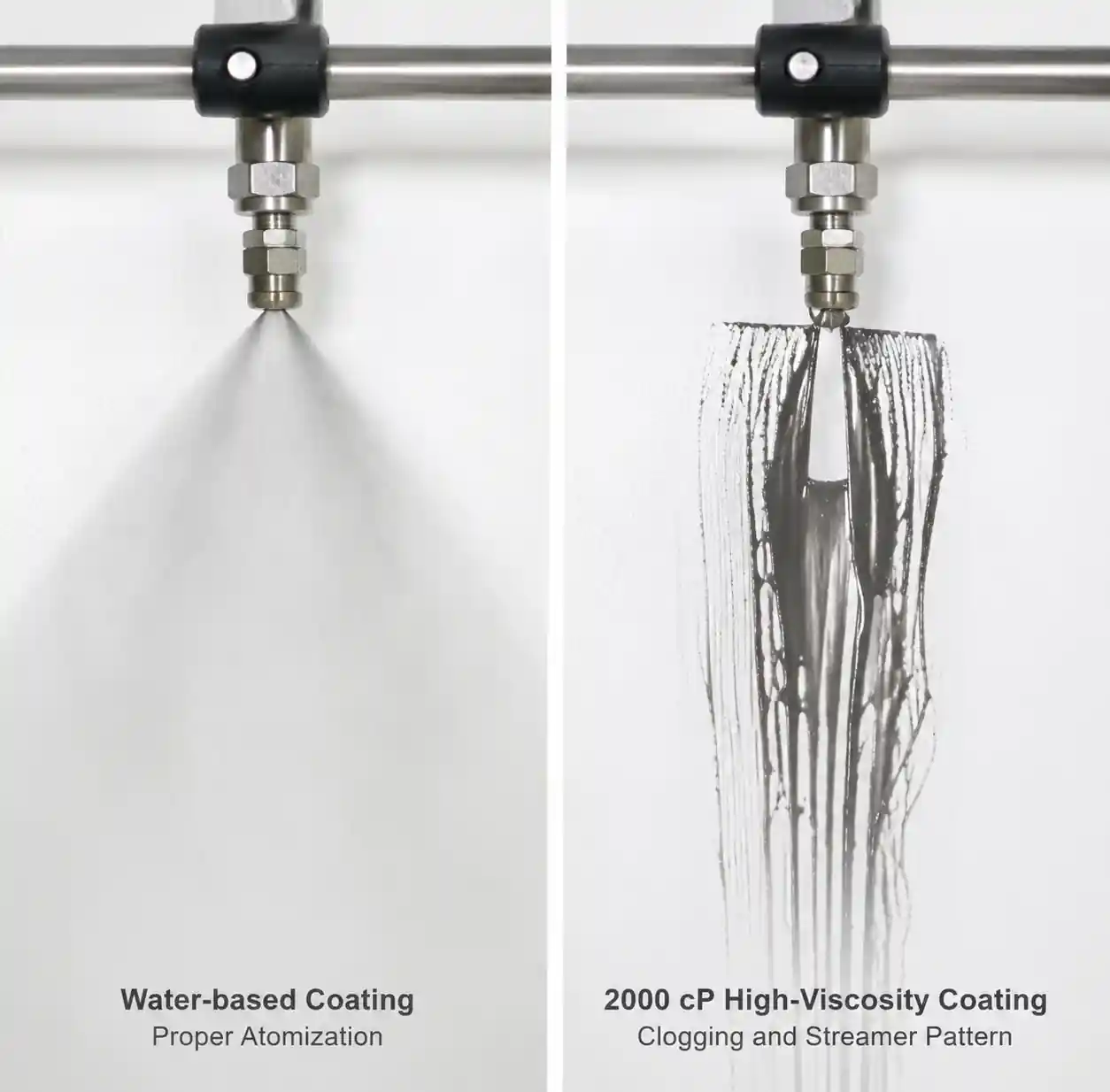
- Q: Why does my spray pattern look good when I test with water but terrible with actual coating?
- Q: How often should I replace nozzles?
- Q: Can I use the same nozzle for multiple coating formulations?
- Q: What's the best way to clean clogged high-flow nozzles?
- 10. Conclusion and Next Actions
- Next Actions
Table of Contents
- Introduction: Why High Viscosity Coatings Challenge Standard Nozzles
- Understanding Flow Dynamics in High Viscosity Applications
- Critical Nozzle Parameters for High Viscosity Fluids
- High-Flow Nozzle Types: Performance Comparison
- Orifice Sizing and Pressure Requirements
- Material Selection for Abrasive High Viscosity Coatings
- Common Installation and Operational Mistakes
- Step-by-Step Selection Process
- FAQ
- Conclusion and Next Actions
1. Introduction: Why High Viscosity Coatings Challenge Standard Nozzles
If you've experienced coating application failures where material simply won't spray, backs up in the feed line, or produces inconsistent coverage patterns, you're likely dealing with inadequate nozzle selection for your viscosity range. High viscosity coatings—typically above 500 cP (centipoise) and especially above 2,000 cP—require fundamentally different nozzle designs than water-based or low-viscosity fluids.
In our field application work with automotive coating lines, industrial roll coating systems, and protective coating operations, we consistently see three failure modes: complete flow blockage at target pressure (fluid won't atomize), severe pattern distortion (oval or streaky instead of uniform fan), and premature nozzle wear from forcing undersized orifices. Each failure represents lost production time, wasted material, and rework costs that typically exceed $2,000–$8,000 per incident in mid-scale operations.
This guide provides engineering-level selection criteria based on fluid mechanics principles, comparative performance data from multiple nozzle configurations, and economic analysis of orifice sizing decisions. You'll learn how to calculate minimum orifice diameter from viscosity and desired flow rate, compare air-assisted versus hydraulic atomization for your specific coating, select wear-resistant materials that won't enlarge the orifice beyond spec, and avoid the three most common installation errors that reduce effective flow capacity by 30–50%.
What you will achieve: By the end of this article, you'll have a repeatable method to specify nozzles that reliably spray coatings up to 5,000 cP, maintain pattern uniformity within ±10% across the spray width, and deliver predictable service life in abrasive or filled coating formulations.
2. Understanding Flow Dynamics in High Viscosity Applications
2.1 Reynolds Number and Laminar Flow Regime
Standard hydraulic spray nozzles assume turbulent flow inside the orifice (Reynolds number Re > 4,000), which creates the instability needed for breakup into droplets. For high viscosity fluids, Reynolds number drops dramatically:
Re = (ρ × v × D) / μ
Where:
- ρ = fluid density (kg/m³)
- v = velocity through orifice (m/s)
- D = orifice diameter (m)
- μ = dynamic viscosity (Pa·s)
A coating with 2,000 cP viscosity (2.0 Pa·s) at density 1,200 kg/m³ flowing through a 1.5 mm orifice at 3 m/s yields Re ≈ 2,700—firmly in the laminar regime. Laminar flow produces a coherent liquid stream rather than atomized spray. To reach Re > 4,000 with this viscosity, you need either higher velocity (which requires impractical pressure—often exceeding 150 bar / 2,175 psi) or larger orifice diameter, which increases droplet size and may compromise coating quality.
2.2 Pressure-Flow Relationship Deviation
The standard nozzle formula Q = K√P assumes Newtonian fluid with negligible viscosity effects. For high viscosity coatings, actual flow deviates 15–40% below predicted values because:
- Viscous resistance dominates pressure drop in the orifice entry and vena contracta region
- Non-Newtonian behavior (shear-thinning or thixotropic) means effective viscosity changes with shear rate through the orifice
- Wall slip in filled coatings (pigments, fillers) creates a lubricating layer that partially recovers flow
From our pressure-flow testing with epoxy coatings (1,500–3,000 cP), we measured 25–35% flow reduction compared to water-calibrated K values at the same pressure. This means you cannot reliably use manufacturer flow charts developed for water unless they provide viscosity correction factors—most do not.
2.3 Atomization Energy Requirements
Achieving acceptable droplet size (typically 50–200 microns for coating applications) requires surface energy to create new liquid surface area. For a viscous fluid, this energy comes from:
- Hydraulic pressure energy converted to kinetic energy at the orifice exit
- Air shear energy in air-assisted or airless air-assisted nozzles
- Mechanical energy in rotary atomizers (not covered here)
Energy required scales with surface tension and viscosity. A 2,000 cP coating requires roughly 4–6× more atomization energy than a 100 cP coating to achieve the same droplet size distribution. This is why high viscosity coatings often need specialized nozzle designs or air assistance even when flow rate alone doesn't require it.
3. Critical Nozzle Parameters for High Viscosity Fluids
When selecting nozzles for high viscosity coatings, five parameters dominate performance:
3.1 Orifice Diameter (Most Critical)
Minimum practical orifice diameter is determined by viscosity and acceptable pressure:
D_min ≈ 0.15 × (μ / ρ)^0.3
This empirical relationship (from coating industry practice) suggests that for 2,000 cP coatings, orifice diameter should be at least 1.8–2.0 mm to avoid excessive pressure requirements. Going smaller forces you above 100 bar (1,450 psi), which is often beyond the capability of standard coating pumps and creates safety concerns with hose connections.
3.2 Spray Angle
High viscosity fluids produce narrower spray angles than water at the same nozzle geometry. A nozzle rated "80° with water" typically delivers 55–65° with 2,000 cP coating. This angle reduction means:
- Reduced coverage width per nozzle pass
- Need for reduced nozzle spacing (typically 20–30% closer)
- Potential for streak patterns if spacing isn't adjusted
For roll coating and flat panel applications, we typically specify 65–80° rated angle with water, knowing you'll get 50–65° effective angle with high viscosity coatings—still adequate for uniform coverage with proper overlap.
3.3 Flow Rate Capacity
High-flow nozzles for coatings typically range from 2 to 20 L/min (0.5 to 5.3 GPM) at working pressure. Flow rate selection depends on:
- Web speed or substrate travel rate (m/min)
- Target coating thickness (wet film thickness in microns)
- Coverage width per nozzle
- Number of nozzles in the manifold
A common mistake is selecting flow rate based solely on total system capacity, then discovering individual nozzle velocities are too low to atomize the viscous coating. Each nozzle should operate at sufficient velocity for your viscosity—typically 8–15 m/s exit velocity for 1,000–3,000 cP coatings.
3.4 Internal Flow Passage Design
High-flow nozzles use three main internal geometries:
- Straight-bore orifice: Simplest, lowest cost, but highest pressure requirement and poorest atomization quality for viscous fluids
- Venturi or converging passage: Reduces pressure requirement by 20–30%, improves flow stability, standard choice for most high viscosity applications
- Turbulence chamber design: Pre-swirl chamber creates rotational energy, better atomization, but more sensitive to viscosity variation
For coatings above 1,500 cP, we strongly recommend venturi or turbulence chamber designs. The added cost (typically $15–$40 per nozzle) is recovered in reduced pump size and energy consumption.
3.5 Connection Type and Feed Path
Often overlooked: the connection from supply line to nozzle creates additional flow resistance. For high viscosity fluids:
- Use full-port connections (no diameter reduction)
- Minimize number of elbows and direction changes
- Specify nozzles with large inlet passages (minimum 1.5× orifice diameter)
- Consider manifold block designs that feed nozzles from the back rather than threaded side connections
We've diagnosed several "nozzle problems" that were actually 50–70% flow restriction in 1/8" NPT adapters upstream of perfectly adequate nozzles.
4. High-Flow Nozzle Types: Performance Comparison
4.1 Hydraulic Flat Fan Nozzles
| Parameter | Performance with High Viscosity |
|---|---|
| Viscosity range | Up to 3,000 cP (practical limit ~2,000 cP for quality atomization) |
| Typical flow rate | 2–12 L/min at 40–100 bar |
| Droplet size (Dv50) | 150–400 microns (increases significantly with viscosity) |
| Spray angle retention | Poor: 60–75% of water-rated angle |
| Pressure requirement | High: 60–120 bar for acceptable atomization |
| Atomization quality | Fair to good below 1,500 cP; poor above 2,500 cP |
| Cost per nozzle | $25–$80 (ceramic or carbide insert) |
| Best application | Moderate viscosity coatings, wide web coating, where some droplet size variation acceptable |
Hydraulic flat fan nozzles work by forcing fluid through an elliptical orifice or internal vane that creates a flat sheet. As viscosity increases, the sheet becomes more coherent (less prone to breakup), resulting in larger droplets and narrower spray angle. For coatings above 2,000 cP, you'll typically need 80–100 bar (1,160–1,450 psi) to achieve acceptable atomization, which pushes the limits of standard coating pumps.
Field observation: In automotive primer application (1,800 cP), we measured spray width reduction from 300 mm to 210 mm when switching from water to actual coating at same nozzle and pressure. This required reducing nozzle spacing from 250 mm to 180 mm centers to maintain overlap.
4.2 Air-Assisted Airless Nozzles
| Parameter | Performance with High Viscosity |
|---|---|
| Viscosity range | Up to 8,000 cP (practical limit for most designs) |
| Typical flow rate | 1–8 L/min at 30–80 bar fluid + 2–4 bar air |
| Droplet size (Dv50) | 50–150 microns (significantly better than hydraulic alone) |
| Spray angle retention | Good: 80–95% of rated angle |
| Pressure requirement | Moderate: 30–80 bar fluid (air assists atomization) |
| Atomization quality | Excellent even at 3,000+ cP |
| Cost per nozzle | $120–$350 (requires dual-feed manifold) |
| Best application | High viscosity coatings requiring fine atomization, automotive, aerospace, high-end finishing |
Air-assisted airless (AAA) nozzles combine hydraulic pressure (30–80 bar) with low-pressure air (2–4 bar) injected at the orifice exit. The air stream shears the fluid, dramatically improving atomization. This technology reduces required fluid pressure by 40–60% compared to hydraulic-only atomization for the same droplet size.
Key advantage: AAA nozzles maintain consistent spray pattern even as coating viscosity varies ±30% due to temperature changes during production. The air flow compensates for viscosity variation.
Key disadvantage: Requires compressed air supply (typically 0.5–1.5 m³/min per nozzle at 4 bar), adding infrastructure cost and complexity.
4.3 Full Cone and Hollow Cone Nozzles
Generally not recommended for high viscosity coating applications due to:
- Internal swirl chambers that create high viscous resistance
- Small flow passages prone to clogging with filled coatings
- Circular pattern not suited to web or panel coating geometries
Exception: Some specialty roll coating applicators use modified hollow cone designs for curtain coating where the circular pattern is spread into a sheet before contacting the web.
4.4 Performance Summary Table
| Nozzle Type | Max Practical Viscosity | Atomization Quality (1–5) | Pressure Requirement | Infrastructure Complexity | Typical Cost |
|---|---|---|---|---|---|
| Hydraulic Flat Fan | 2,000 cP | 3 | High (80–120 bar) | Low | $25–$80 |
| Hydraulic Flat Fan (large orifice) | 3,500 cP | 2 | Very High (100–150 bar) | Low | $35–$95 |
| Air-Assisted Airless | 8,000 cP | 5 | Moderate (30–80 bar) | High (air system) | $120–$350 |
| Airless (large orifice) | 5,000 cP | 2–3 | High (100–150 bar) | Low | $45–$120 |
Atomization Quality Scale: 1=Poor (ligaments/streams), 5=Excellent (uniform droplet distribution)
After this table: For most industrial high-viscosity coating applications in the 1,500–3,000 cP range, we recommend starting evaluation with large-orifice (2.0–3.0 mm) hydraulic flat fan nozzles if your pump can deliver 80–100 bar. If atomization quality is insufficient (visible streaks, excessive orange peel, or droplet size above 300 microns), upgrade to air-assisted airless. The pressure reduction with AAA typically allows pump downsizing that offsets 40–60% of the added nozzle cost over a 3-year equipment life.
5. Orifice Sizing and Pressure Requirements
5.1 Calculating Minimum Orifice Size
For a given coating viscosity and desired flow rate, minimum orifice diameter can be estimated from:
D_min = √(8 × Q × μ / (π × ΔP × C_d))
Where:
- D_min = minimum orifice diameter (m)
- Q = desired flow rate (m³/s)
- μ = dynamic viscosity (Pa·s)
- ΔP = available pressure drop (Pa)
- C_d = discharge coefficient (~0.6–0.7 for viscous flow)
Worked example:
- Target flow: 6 L/min = 0.0001 m³/s
- Viscosity: 2,000 cP = 2.0 Pa·s
- Available pressure: 80 bar = 8,000,000 Pa
- C_d ≈ 0.65
D_min = √(8 × 0.0001 × 2.0 / (π × 8,000,000 × 0.65)) ≈ 0.00222 m = 2.2 mm
This calculation suggests a 2.2 mm orifice minimum. In practice, we'd specify 2.5 mm to provide margin for viscosity variation and coating buildup on orifice edges over time.
5.2 Pressure Selection Trade-Offs
| Pressure Range | Advantages | Disadvantages | Recommended Application |
|---|---|---|---|
| 30–50 bar (435–725 psi) | Standard coating pumps; safe for rubber hose; easy to control | Requires very large orifices (3–4 mm); poor atomization above 1,500 cP | Low-end coatings, adhesives where droplet size not critical |
| 60–100 bar (870–1,450 psi) | Good compromise: adequate atomization with 2.0–2.5 mm orifice; reasonable pump cost | Requires reinforced hose; safety considerations | Most common choice for 1,500–3,000 cP industrial coatings |
| 100–150 bar (1,450–2,175 psi) | Allows smaller orifices; better atomization | Expensive high-pressure pumps; safety concerns; accelerated wear on seals and fittings | High-end finish coatings; aerospace applications |
| 150+ bar (2,175+ psi) | Excellent atomization even at high viscosity | Very expensive equipment; significant safety requirements; rapid component wear | Specialty applications only; usually more cost-effective to switch to air-assisted |
After this table: The "sweet spot" for most high viscosity coating operations is 70–90 bar. This pressure range allows 2.0–2.5 mm orifices for coatings up to 2,500 cP, works with mid-range coating pumps ($3,000–$8,000), and doesn't require special safety equipment beyond standard high-pressure hose and proper manifold design.
5.3 Avoiding the "Double Pressure" Trap
A common misconception: if coating won't spray at 60 bar, doubling to 120 bar will fix it. Reality:
- Flow increases only by √2 = 1.41× (41% increase, not 100%)
- If the orifice is too small for the viscosity, increased pressure creates higher shear heating, potentially degrading the coating
- Pressure above 100 bar significantly accelerates wear, particularly with filled coatings
If coating won't spray adequately at your target pressure, the correct solution is usually larger orifice, not higher pressure. We've seen numerous cases where switching from 1.5 mm to 2.5 mm orifice at the same 70 bar pressure transformed a non-functional system into a production line running within spec.
6. Material Selection for Abrasive High Viscosity Coatings
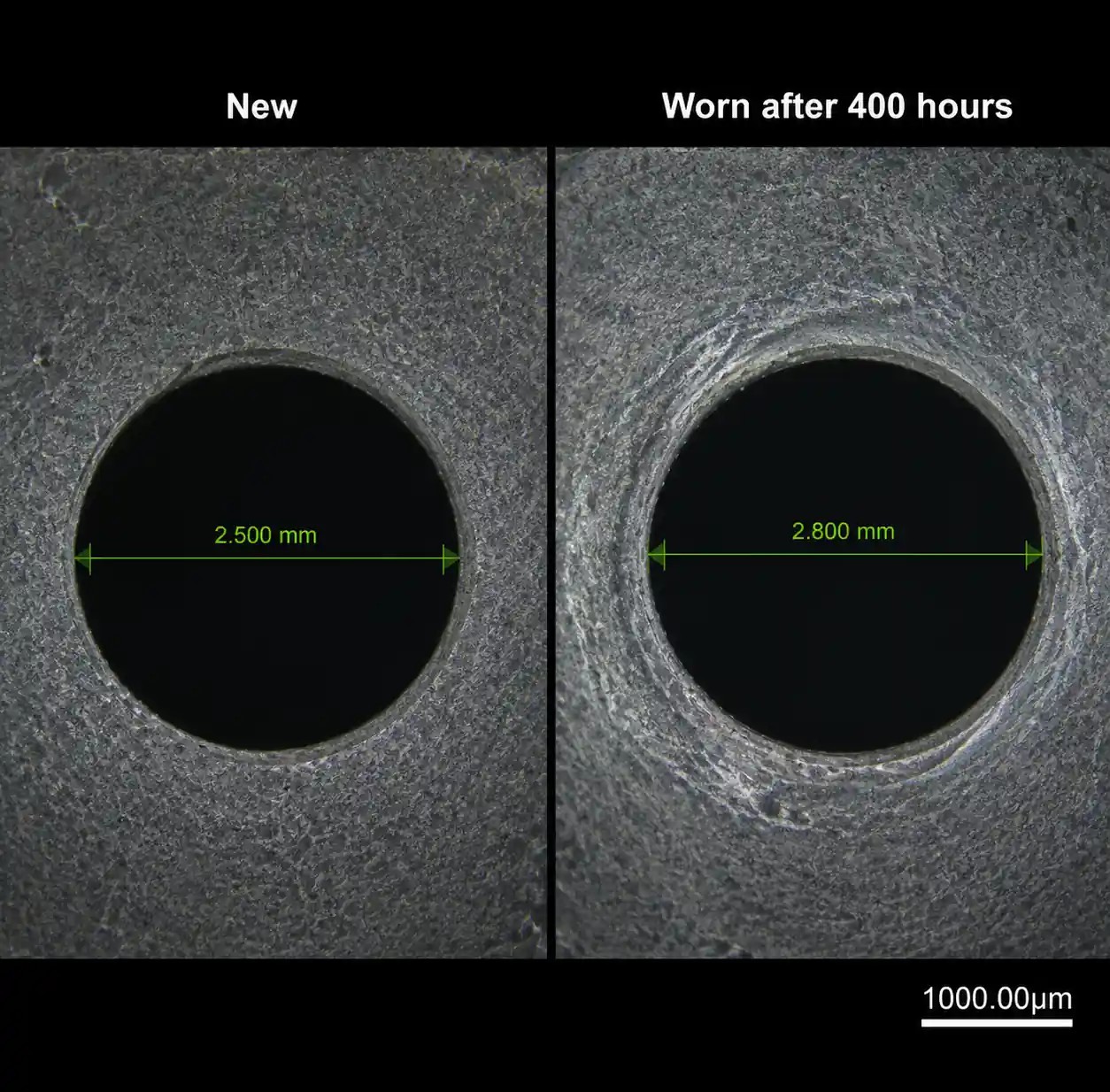
High viscosity coatings often contain abrasive fillers (TiO2, silica, aluminum oxide, zinc, etc.) that erode the orifice. As orifice diameter increases by wear, flow rate increases and spray pattern distorts. Material selection is critical for predictable service life.
6.1 Wear Rate Comparison
| Material | Hardness (HV) | Relative Wear Life* | Cost Multiple vs. Stainless | Typical Service Life | Best Application |
|---|---|---|---|---|---|
| 303 Stainless Steel | 150–200 | 1× (baseline) | 1× | 200–400 hours | Water-based, non-abrasive coatings only |
| Hardened 440C Stainless | 550–600 | 3–4× | 1.5× | 600–1,600 hours | Low to moderate abrasive content |
| Tungsten Carbide Insert | 1,400–1,600 | 12–18× | 4–6× | 2,400–7,200 hours | Moderate to high abrasive coatings |
| Silicon Carbide (SiC) | 2,400–2,600 | 25–40× | 6–8× | 5,000–16,000 hours | High abrasive content; excellent for TiO2-filled |
| Sapphire (Al2O3) | 2,000–2,200 | 30–50× | 10–15× | 6,000–20,000 hours | Highest wear resistance; premium applications |
*Relative wear life tested with 15% TiO2-filled epoxy coating at 2,000 cP, 80 bar pressure, 2.5 mm orifice
Service life defined as time until flow rate increases >15% due to orifice enlargement
After this table: The key insight from our wear testing: total cost of ownership favors ceramic materials above ~1,500 operating hours. A silicon carbide nozzle costs 6× more but lasts 25–40× longer, meaning cost per operating hour is actually 75–85% lower than stainless steel. For continuous or high-volume batch coating operations, ceramic nozzles pay for themselves in 3–8 months.
6.2 Brittle Failure Risk
Ceramic materials (tungsten carbide, silicon carbide, sapphire) are brittle. We've documented failures from:
- Pressure spikes above rated pressure (e.g., pump cavitation surge, valve slamming)
- Thermal shock (rapid temperature change >40°C)
- Installation over-torque (crushed insert)
- Impact during cleaning (dropped parts, high-pressure water jet)
Recommended practice: For ceramic nozzles, install pressure relief valves set to 115% of maximum operating pressure, use torque wrench for installation (12–15 N·m typical for 1/4" NPT ceramic insert nozzles), and train maintenance staff on proper handling.
7. Common Installation and Operational Mistakes
From field service calls on underperforming coating systems, here are the three most frequent errors:
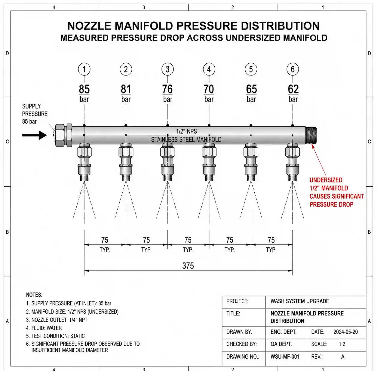
7.1 Undersized Feed Manifold
Problem: Nozzles are adequately sized, but manifold supplying them is too small. A 1/2" NPT manifold feeding six 6 L/min nozzles (total 36 L/min) creates 30–40% pressure drop in the manifold itself, leaving insufficient pressure at the last nozzles.
Solution: Manifold internal diameter should be sized for <5% pressure drop at total flow. For high viscosity coatings, this typically means:
- Up to 20 L/min total: 3/4" manifold minimum
- 20–50 L/min total: 1" manifold
- 50–100 L/min total: 1-1/4" or 1-1/2" manifold
Use manifold pressure taps to measure pressure at first and last nozzle positions. If pressure drop exceeds 5 bar across the manifold, upsize it.
7.2 Ignoring Temperature Effects on Viscosity
Coating viscosity changes dramatically with temperature. A typical epoxy coating at 2,000 cP at 20°C may be 800 cP at 30°C and 500 cP at 40°C. This means:
- Spray pattern changes throughout the day as coating temperature drifts
- First-shift pattern doesn't match third-shift pattern
- Summer/winter performance variation
Solution: Install in-line temperature monitoring and either (a) temperature-control the coating feed with heat exchanger to ±2°C, or (b) use air-assisted nozzles which compensate for viscosity variation. Most production coating lines above $100K investment should include temperature control.
7.3 Using Water-Based Flow Charts for Viscous Coatings
Nozzle manufacturers publish flow-vs-pressure charts developed with water. Applying these charts directly to 2,000 cP coatings results in 25–40% flow under-prediction, leading to incorrect nozzle selection.
Solution: Request viscosity-corrected flow data from the manufacturer, or conduct your own flow testing with actual coating at installation. We typically test three nozzles from each batch at 80%, 100%, and 120% of target pressure with actual coating and average the results to establish baseline flow rates for production calibration.
8. Step-by-Step Selection Process
Step 1: Define Requirements
Document:
- Coating viscosity range (minimum and maximum expected)
- Coating temperature at spray application
- Required flow rate per nozzle (L/min)
- Coverage width required
- Substrate type and travel speed
- Acceptable droplet size range
- Coating formulation (abrasive filler content, particle size)
Step 2: Calculate Minimum Orifice Diameter
Using formula from Section 5.1 or manufacturer guidelines, determine minimum orifice for your viscosity and target pressure range.
Step 3: Select Nozzle Type
Decision tree:
- Viscosity <1,500 cP: Standard hydraulic flat fan, 1.8–2.5 mm orifice
- Viscosity 1,500–3,000 cP: Large-orifice hydraulic flat fan (2.0–3.0 mm) OR air-assisted airless if atomization quality critical
- Viscosity 3,000–5,000 cP: Air-assisted airless strongly recommended
- Viscosity >5,000 cP: Air-assisted airless or consider alternate application method (roll coating, curtain coating)
Step 4: Select Material Based on Operating Hours
- <500 hours/year: Hardened stainless acceptable
- 500–2,000 hours/year: Tungsten carbide cost-effective
-
2,000 hours/year: Silicon carbide or sapphire lowest total cost
Step 5: Verify Pressure and Flow Capacity
Check that your coating pump can deliver required pressure × total flow rate for all nozzles. Include 20% margin for pressure drop in lines and manifold.
Step 6: Design Manifold and Spacing
- Calculate spray width from viscosity-adjusted spray angle
- Set nozzle spacing for 30–50% overlap at target spray distance
- Size manifold for <5% pressure drop
- Include pressure gauge taps at first and last nozzle
Step 7: Conduct Flow Testing
Before full production:
- Measure actual flow rate at operating pressure with your coating
- Compare spray pattern to water-based testing
- Adjust spacing if needed
- Establish baseline flow rates for wear monitoring
Step 8: Set Up Wear Monitoring
Record flow rate weekly. When flow increases >15%, plan nozzle replacement before pattern quality degrades.
9. FAQ
Q: Can I just increase pressure if my coating won't spray?
No—pressure increases flow only by square-root relationship (Q ∝ √P). If the orifice is too small for your viscosity, higher pressure creates excessive shear heating and accelerates wear without solving the atomization problem. Correct solution: larger orifice.
Q: How much does air-assisted airless add to operating cost?
Compressed air typically costs $0.02–$0.04 per m³ depending on your facility. For a nozzle using 1 m³/min air at $0.03/m³, operating cost is $1.80/hour. This is usually negligible compared to coating material cost ($15–$80/hour typical) and labor. The real cost is infrastructure: air supply plumbing, filtration, and manifold complexity.
Q: Why does my spray pattern look good when I test with water but terrible with actual coating?
Water is 1 cP; your coating is 1,500–3,000 cP. Viscosity dramatically affects atomization quality, spray angle, and droplet size. Always test with actual coating at operating temperature before finalizing nozzle selection.
Q: How often should I replace nozzles?
Monitor flow rate. Replace when flow increases >15% from baseline—this indicates orifice wear has started to affect pattern uniformity. For stainless steel with abrasive coatings, this may be 200–400 hours. For ceramic, 5,000–15,000 hours.
Q: Can I use the same nozzle for multiple coating formulations?
Only if viscosities are within ±30% and filler types are compatible. Switching from non-abrasive to abrasive coating without changing material will dramatically shorten nozzle life. Switching from 1,000 cP to 2,500 cP coating will change spray pattern and may prevent adequate atomization.
Q: What's the best way to clean clogged high-flow nozzles?
For production cleaning: reverse-flush with solvent at 2–3× operating pressure. For deep cleaning: ultrasonic bath in appropriate solvent for 15–30 minutes. Never use wire or tools to mechanically clean orifice—this damages the precision edge and ruins spray pattern. If ultrasonic cleaning doesn't restore flow, replace the nozzle.
10. Conclusion and Next Actions
Successfully spraying high viscosity coatings requires matched consideration of orifice size, pressure, nozzle internal geometry, and material selection. The most common failure mode—coating won't spray or produces poor pattern—usually traces to undersized orifice for the viscosity, not insufficient pressure.
Key takeaways:
-
Orifice diameter is the critical parameter. For 2,000 cP coatings, specify minimum 2.0–2.5 mm orifice even if this seems large compared to water-based nozzles.
-
Pressure range of 70–90 bar is the practical sweet spot for most high viscosity industrial coatings, balancing atomization quality with equipment cost and safety.
-
Air-assisted airless technology extends capability to 8,000+ cP with significantly better atomization than hydraulic-only designs, at the cost of added infrastructure.
-
Material selection determines total cost of ownership. For abrasive coatings in continuous operation, ceramic materials (silicon carbide, tungsten carbide) deliver 75–85% lower cost per operating hour despite 4–8× higher initial purchase price.
-
Never use water-based flow charts for viscous coating selection—actual flow will be 25–40% lower, leading to undersized nozzle specification.
Next Actions
Immediate: Measure your coating viscosity at actual spray temperature (not room temperature) using a Brookfield viscometer or equivalent. Document viscosity range across your production batch variation.
For existing systems with spray problems: Check three things first: (1) actual operating pressure at the nozzle (not just pump pressure), (2) manifold pressure drop from first to last nozzle, and (3) orifice diameter relative to viscosity guidelines in Section 5.
For new system design: Conduct laboratory spray testing with sample nozzles using your actual coating before finalizing manifold design. Test at ±20% of target viscosity to verify performance across expected variation.
Need assistance? For nozzle selection specific to your coating formulation, substrate, and quality requirements, contact your coating equipment supplier or nozzle manufacturer with: coating viscosity at spray temperature, required coverage rate (m²/min), acceptable droplet size range, and annual operating hours. Request flow testing with your coating sample if possible.