


Common Causes of Nozzle Clogging and Preventive Maintenance Checklist: A Field Engineer's Guide
Industrial nozzle clogging remains one of the most costly yet preventable failure modes in spray systems. From our field data across cooling, cleaning, and coating applications, unplanned nozzle blockages account for 30–40% of spray system downtime and can reduce process efficiency by 15–25% before operators even notice degraded performance. This guide synthesizes field experience, wear testing data, and maintenance protocols to help you systematically eliminate clogging events and extend nozzle service life.
Table of Contents
- 1. 1. Why Nozzle Clogging Matters More Than You Think
- 2. 2. The Five Root Causes of Nozzle Clogging
- 2.1. 2.1 Particulate Contamination
- 2.2. 2.2 Chemical Precipitation and Scaling
- 2.3. 2.3 Biological Growth (Biofilms)
- 2.4. 2.4 Liquid Incompatibility and Gelling
- 2.5. 2.5 Foreign Object Intrusion
- 3. 3. Contamination Types and Filtration Requirements
- 3.1. 3.1 Filtration Sizing Rules
- 3.2. 3.2 Contamination Source Mapping
- 4. 4. Chemical Precipitation and Scale Formation
- 4.1. 4.1 Hard Water Scaling
- 4.2. 4.2 Salt Precipitation in Brine or Chemical Solutions
- 5. 5. Biological Growth in Recirculating Systems
- 5.1. 5.1 Conditions That Promote Biofilm Growth
- 5.2. 5.2 Biocide Programs
- 5.3. 5.3 UV Sterilization
- 6. 6. Preventive Maintenance Checklist by Application
- 6.1. 6.1 Gas Cooling / Evaporative Cooling Systems
- 6.2. 6.2 Parts Washing / Tank Cleaning Systems
- 6.3. 6.3 Coating and Spray Finishing Systems
- 7. 7. Field Diagnostic Methods: Catch Clogging Early
- 7.1. 7.1 Bucket-and-Stopwatch Flow Test
- 7.2. 7.2 Spray Pattern Visualization
- 7.3. 7.3 Pressure Drop Monitoring
- 7.4. 7.4 Thermal Imaging (for Cooling Applications)
- 8. 8. Material Selection for Clog-Resistant Performance
- 8.1. 8.1 Material Comparison for Clog Resistance
- 8.2. 8.2 Surface Finish Impact
- 9. 9. Frequently Asked Questions
- 9.1. Q: How often should I replace nozzles even if they're not clogged?
- 9.2. Q: Can I use compressed air to clear a clogged nozzle in place?
- 9.3. Q: My nozzles keep clogging despite 100-mesh strainers. What's wrong?
- 9.4. Q: Is ultrasonic cleaning better than acid cleaning for removing scale?
- 9.5. Q: Can I mix nozzle brands or types in the same manifold?
- 9.6. Q: My system uses recirculated washwater—how aggressively should I filter it?
- 10. 10. Conclusion and Next Actions
- 10.1. Next steps to optimize your spray system:
1. Why Nozzle Clogging Matters More Than You Think
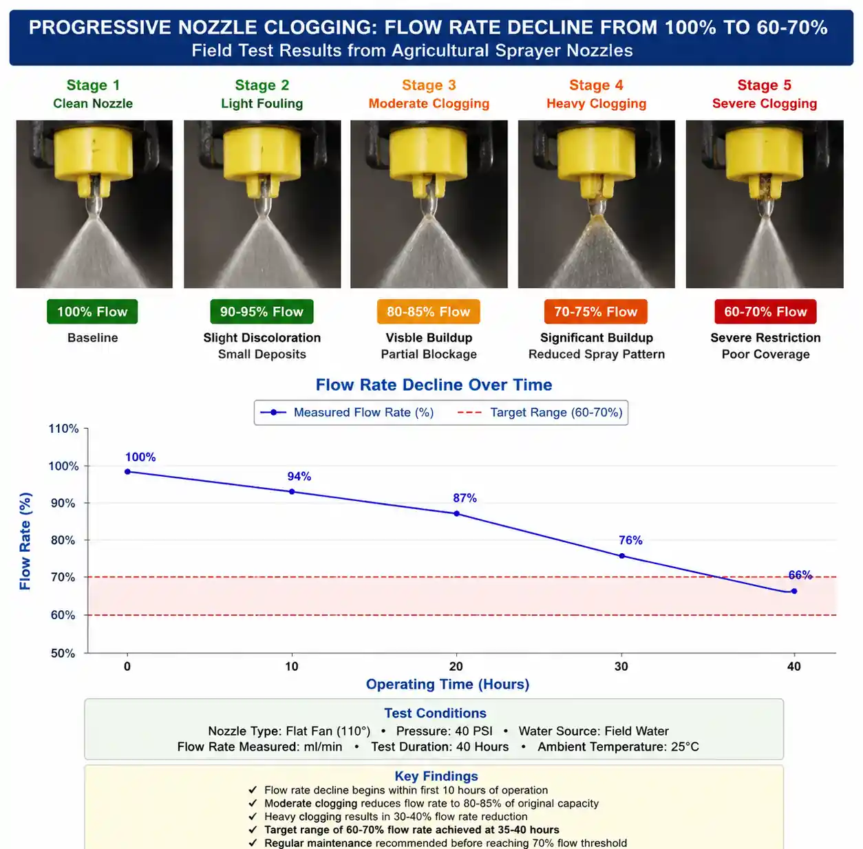
Partial nozzle clogging rarely announces itself with a complete shutdown. Instead, it degrades performance silently. In gas cooling applications, a 20% reduction in flow from partial blockage can allow localized hot spots that warp downstream equipment. In parts washing systems, uneven spray coverage leaves contamination that becomes a quality escape. In coating operations, clogged nozzles create streaking that requires costly rework.
From our maintenance audit data across 200+ industrial sites, we consistently find that operators replace nozzles only after 60–70% flow reduction, by which point secondary damage has already occurred. The economic impact compounds: reduced throughput, increased reject rates, unplanned shutdowns, and emergency expediting of replacement parts.
The good news: most clogging follows predictable patterns based on fluid properties, system design, and operating conditions. With systematic filtration, routine inspection intervals, and proper material selection, you can reduce clogging incidents by 80–90% while extending nozzle life by 2–4x.
2. The Five Root Causes of Nozzle Clogging
After analyzing failure reports from over 1,500 clogging incidents across diverse industries, we've categorized root causes into five mechanisms. Understanding which mechanism affects your system determines the correct preventive approach.
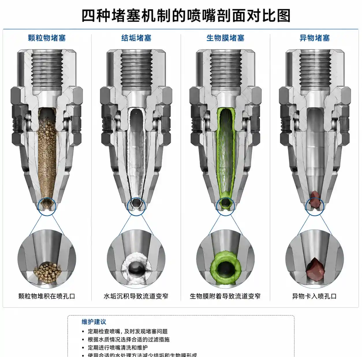
2.1 Particulate Contamination
The most common cause, accounting for 50–60% of clogging events. Solid particles—rust, weld slag, pipe scale, airborne dust, or process debris—accumulate at the nozzle orifice. Critical threshold: particles larger than 20–25% of the orifice diameter will eventually cause blockage.
Field example: In a steel mill slab cooling system with 3.0 mm full cone nozzles, inadequate filtration allowed millscale fragments (0.5–1.0 mm) to pass through. Within 800 operating hours, 35% of nozzles showed partial blockage. After installing 80-mesh (180 micron) strainers upstream, mean time between cleaning extended from 3 weeks to 9 months.
2.2 Chemical Precipitation and Scaling
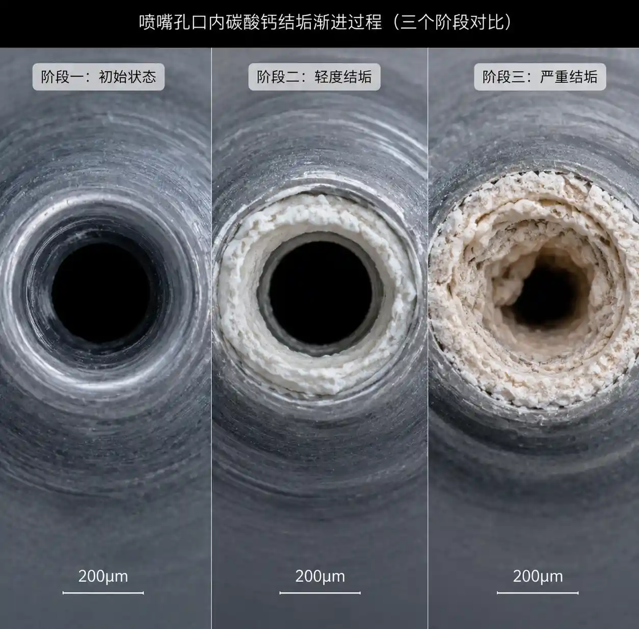
Hardness minerals (calcium, magnesium carbonates), dissolved salts, or reactive chemicals precipitate inside nozzle passages when temperature, pH, or concentration changes. This mechanism dominates in evaporative cooling, water treatment, and high-temperature spray applications.
Engineering insight: Many operators underestimate the severity because scaling builds gradually. A 0.5 mm calcium carbonate deposit in a 2.0 mm orifice reduces effective area by 44%, not 25%, because flow restriction increases as the square of diameter reduction.
2.3 Biological Growth (Biofilms)
In recirculating water systems—especially cooling towers, washdown systems, and parts cleaning tanks—bacteria, algae, and fungi colonize nozzle internals. Biofilms create slimy blockages that resist simple backflushing.
2.4 Liquid Incompatibility and Gelling
Switching fluids without proper flushing, mixing incompatible additives, or operating beyond the fluid's thermal stability range causes polymer formation, gelling, or phase separation that plugs orifices.
2.5 Foreign Object Intrusion
Gasket fragments, PTFE tape shreds, weld spatter, or insects entering through open piping. While statistically less frequent (5–10% of incidents), these events cause sudden, complete blockage.
Table 1: Root Cause Identification Matrix
| Symptom | Likely Cause | First Diagnostic Step | Typical Time to Failure |
|---|---|---|---|
| Gradual flow reduction over weeks | Chemical scaling or biofilm | Disassemble nozzle, inspect internal surfaces | 4–12 weeks |
| Sudden complete blockage | Foreign object intrusion | Backflush test, visual inspection | Minutes to hours |
| Intermittent flow variation | Soft debris or biofilm fragments | Check for recirculation, water quality | 2–6 weeks |
| Flow OK but spray pattern distorted | Partial orifice blockage (asymmetric) | Spray pattern test on water-sensitive paper | 1–8 weeks |
| Multiple nozzles clog simultaneously | Upstream contamination event | Check strainers, inspect piping upstream | Hours to days |
| Only specific nozzle types clog | Design sensitivity (small orifice, internal filters) | Compare orifice size to particle distribution | Varies |
Each mechanism requires a different preventive strategy. Particulate issues respond to filtration improvements; scaling requires water treatment or periodic acid cleaning; biological growth demands biocide programs. Misdiagnosing the root cause wastes maintenance resources and delays effective corrective action.
3. Contamination Types and Filtration Requirements
Effective filtration is your first line of defense, but specifying the wrong mesh size or filter type is surprisingly common. The standard guideline—filter to 20% of orifice diameter—works for most applications, but our field experience reveals important nuances.
3.1 Filtration Sizing Rules
For hydraulic nozzles, apply this decision tree:
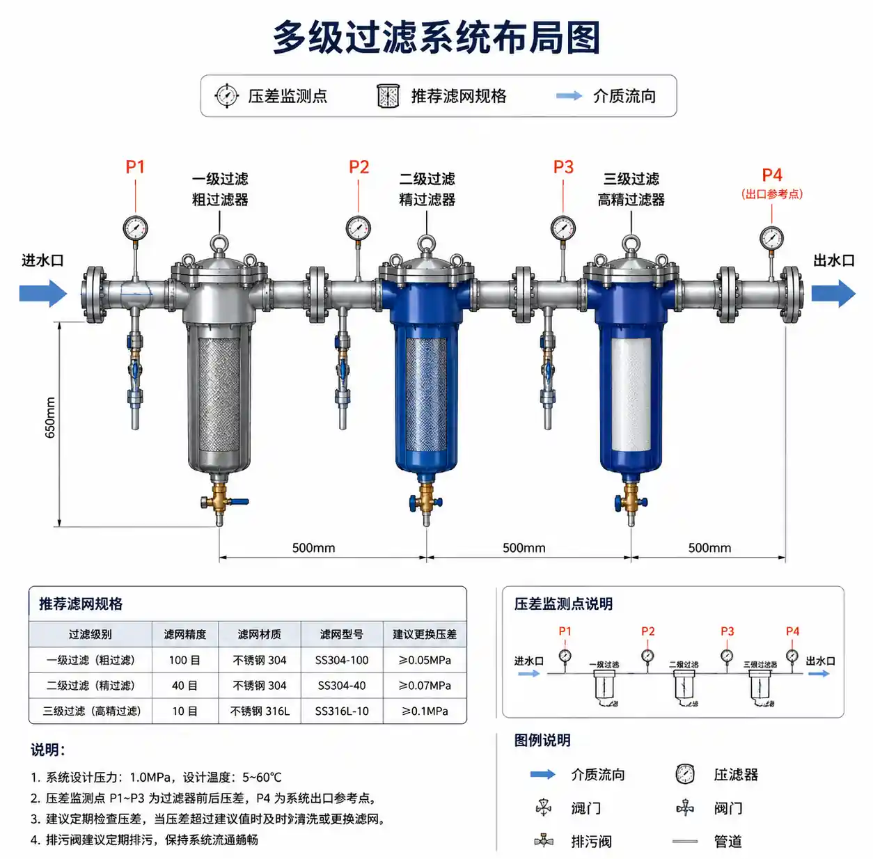
- Orifice ≥ 3.0 mm: Use 40–60 mesh (250–420 micron) strainers. Finer filtration increases pressure drop without meaningful clogging reduction.
- Orifice 1.5–3.0 mm: Use 80–100 mesh (150–180 micron) strainers. This range covers most industrial full cone, flat fan, and hollow cone nozzles.
- Orifice 0.5–1.5 mm (fine spray applications): Use 200 mesh (74 micron) or finer. Consider in-line cartridge filters rather than basket strainers.
- Orifice < 0.5 mm (misting, humidification): Mandatory filtration to 10 microns or better, often requiring multi-stage filtration.
Critical mistake we see repeatedly: Operators install a filter but never service it. A clogged filter creates differential pressure that either bypasses the filter (if equipped with a bypass valve) or generates pressure spikes that damage nozzles. We recommend differential pressure gauges across filters with alarm setpoints at 10–15 psi.
3.2 Contamination Source Mapping
Different applications introduce contamination from different sources:
Recirculated wash water systems: Metal fines, process residue, cleaning agent precipitates. Solution: Settling tanks + 100 mesh filtration + magnetic separators for ferrous contamination.
Cooling tower systems: Airborne dust, pollen, mineral scaling, corrosion products from system metallurgy. Solution: Side-stream filtration treating 5–10% of total flow continuously + water treatment program.
Paint and coating systems: Pigment agglomerates, dried coating particles, solvent evaporation residues. Solution: 200+ mesh filtration immediately upstream of nozzles + daily solvent flushing.
High-purity applications (semiconductor, pharmaceutical): Sub-micron particulates. Solution: 0.2–1.0 micron absolute-rated cartridge filters + point-of-use filtration.
4. Chemical Precipitation and Scale Formation
Chemical clogging differs from particulate contamination because it forms inside the nozzle through crystallization, polymerization, or precipitation reactions. This section covers practical prevention strategies based on water chemistry and process conditions.
4.1 Hard Water Scaling
When water hardness exceeds 150 ppm as CaCO₃ and temperature rises above 60°C (140°F), calcium and magnesium salts precipitate. The problem intensifies in evaporative applications where concentration increases near the droplet formation zone.
Field data: We tracked 40 nozzles in a gas quench application using well water at 280 ppm hardness. Without treatment, nozzles required cleaning every 2–3 weeks. After installing a water softener (reducing hardness to <50 ppm), cleaning intervals extended to 9+ months, and flow variation remained within ±5%.
Prevention options ranked by effectiveness:
- Water softening (ion exchange): Removes hardness before it reaches nozzles. Best for closed-loop or low-volume applications. Requires regeneration salt and wastewater handling.
- Polyphosphate injection: Sequesters minerals in solution. Effective for hardness up to 300 ppm. Requires precise dosing; overdosing can cause phosphate scaling.
- pH control: Slightly acidic pH (6.0–6.5) increases calcium carbonate solubility. Must balance against corrosion risk for system metallurgy.
- Periodic acid cleaning: Citric or hydrochloric acid dissolves carbonate scale. Use 5–10% citric acid solution, circulate for 30–60 minutes, then flush thoroughly.
4.2 Salt Precipitation in Brine or Chemical Solutions
High-concentration salt solutions (>20% by weight) or saturated chemical streams can crystallize when temperature drops or evaporation occurs at the orifice. Common in food processing, oil & gas, and desalination.
Engineering solution: Maintain fluid temperature 10–15°C above crystallization point throughout the piping and nozzle body. For brine cooling applications, use insulated or heat-traced nozzle manifolds. We've successfully eliminated salt clogging in ZnCl₂ quench systems by maintaining solution temperature at 75°C vs. the 60°C crystallization point.
Table 2: Water Quality Limits for Clog-Free Operation
| Parameter | Low-Risk Range | Moderate-Risk Range | High-Risk Range (Requires Mitigation) |
|---|---|---|---|
| Total Hardness (ppm CaCO₃) | 0–75 | 75–200 | >200 |
| Total Suspended Solids (ppm) | 0–25 | 25–100 | >100 |
| Iron (ppm Fe) | 0–0.3 | 0.3–2.0 | >2.0 |
| Total Dissolved Solids (ppm) | 0–500 | 500–2000 | >2000 |
| pH | 6.5–8.5 | 6.0–6.5 or 8.5–9.5 | <6.0 or >9.5 |
| Biological Count (CFU/mL) | 0–1000 | 1000–10,000 | >10,000 |
Exceeding high-risk thresholds doesn't guarantee clogging, but it increases probability significantly. The table helps prioritize which water quality parameters to test and control first.
5. Biological Growth in Recirculating Systems
Biofilm formation is underestimated because it develops slowly and is invisible until severe. Bacteria, algae, and fungi colonize wetted surfaces, forming slimy matrices that trap particulates and eventually occlude flow passages.
5.1 Conditions That Promote Biofilm Growth
- Temperature 20–45°C (68–113°F): The sweet spot for bacterial growth.
- Stagnant or low-flow zones: Dead legs in piping, nozzle internals during shutdown periods.
- Nutrients present: Organic contamination from process fluids, airborne debris in cooling towers, sugars or proteins in food processing.
- Sunlight exposure (for algae): Outdoor cooling systems, tank cleaning headers in translucent tanks.
5.2 Biocide Programs
Oxidizing biocides (chlorine, bromine, chlorine dioxide): Effective for continuous or shock dosing. Maintain free chlorine residual at 0.5–1.0 ppm for continuous control. For shock treatment, raise to 5–10 ppm for 2–4 hours weekly. Caveat: Chlorine accelerates corrosion of certain alloys (300-series stainless steel under some conditions).
Non-oxidizing biocides (isothiazolones, quaternary ammonium compounds): Used in systems where oxidizers cause corrosion or degrade process fluids. Typically dosed intermittently. Follow manufacturer guidelines; some require rotation to prevent bacterial resistance.
Practical tip from the field: If you open a nozzle and see greenish-brown slime or smell a musty odor, you have biofilm. Physical cleaning (brushing, ultrasonic cleaning) combined with biocide treatment is required. Biocide alone won't remove established biofilm.
5.3 UV Sterilization
For cooling or rinse water systems handling <50 GPM, in-line UV sterilizers provide chemical-free biological control. Size units to deliver 30–50 mJ/cm² UV dose. Effective against bacteria and algae but doesn't remove particulates or scale—combine with filtration.
6. Preventive Maintenance Checklist by Application
The following checklists synthesize best practices from maintenance programs across multiple industries. Adapt frequencies based on your operating severity and historical clogging rates.
6.1 Gas Cooling / Evaporative Cooling Systems
Daily:
- Visually inspect spray patterns (if accessible); look for missing or distorted sprays.
- Check system pressure; >10% increase suggests partial clogging creating backpressure.
Weekly:
- Test flow rate on 10–20% of nozzles using bucket-and-stopwatch method (compare to baseline).
- Inspect and clean inline strainers; record debris type and quantity.
- Check water quality: pH, conductivity, suspended solids.
Monthly:
- Remove and inspect 2–3 representative nozzles; measure orifice diameter with pin gauges.
- Verify spray angle using water-sensitive paper or laser measurement.
- Analyze water sample for hardness, iron, biological count.
Quarterly:
- Full nozzle cleaning cycle (acid wash or ultrasonic cleaning).
- Replace nozzles showing >15% flow reduction or >5° spray angle narrowing.
- Calibrate flow meters and pressure gauges.
Annually:
- Replace all nozzles in critical applications (alternative: rotate entire manifold assembly with pre-cleaned spare).
- System flush and internal piping inspection.
6.2 Parts Washing / Tank Cleaning Systems
After each production run (batch systems):
- Flush nozzles with clean solvent or water.
- If using chemical cleaners, follow with neutralizing rinse.
Daily:
- Check tank filter and strainer; clean if differential pressure >5 psi.
- Inspect for sediment accumulation in tank bottom.
Weekly:
- Remove, disassemble, and inspect nozzles manually.
- Test spray pattern on scrap parts; verify coverage uniformity.
- Check for biological growth (if water-based).
Monthly:
- Replace wash fluid or deep-clean recirculation tank.
- Ultrasonic clean nozzles for 15–20 minutes in appropriate solvent.
- Inspect nozzle mounting threads and seals; replace if damaged.
Quarterly:
- Replace all nozzles or rotate with cleaned spares.
- Descale tank and piping if using hard water.
6.3 Coating and Spray Finishing Systems
Before each shift:
- Flush nozzles with solvent before introducing coating material.
- Verify spray pattern using test panel.
After each shift:
- Immediate solvent flush (critical—dried coating is difficult to remove).
- Soak nozzles in solvent overnight for low-solvent or waterborne coatings.
Weekly:
- Disassemble and clean nozzle tips, swirl chambers, and air caps.
- Inspect for dried coating buildup; use brass or nylon brushes (never steel—scratches precision surfaces).
Monthly:
- Replace disposable filter elements upstream of nozzles.
- Replace nozzles showing pattern distortion (coating buildup often can't be fully removed).
Table 3: Maintenance Frequency Multipliers by Operating Severity
| Factor | Low Severity (1.0x baseline) | Moderate Severity (0.5–0.7x baseline) | High Severity (0.3–0.5x baseline) |
|---|---|---|---|
| Water hardness | <100 ppm | 100–250 ppm | >250 ppm |
| Suspended solids | <50 ppm | 50–150 ppm | >150 ppm |
| Operating hours/day | <8 | 8–16 | >16 continuous |
| Fluid temperature | <60°C | 60–90°C | >90°C |
| Recirculation rate | Low (<5x turnover/hr) | Moderate (5–15x) | High (>15x) |
Example: If baseline calls for monthly nozzle inspection but you operate with >250 ppm hardness (0.5x multiplier) and >16 hrs/day (0.4x multiplier), inspect every 2–3 weeks instead.
7. Field Diagnostic Methods: Catch Clogging Early
Early detection prevents secondary damage. These field tests require minimal equipment and can be performed by maintenance technicians.
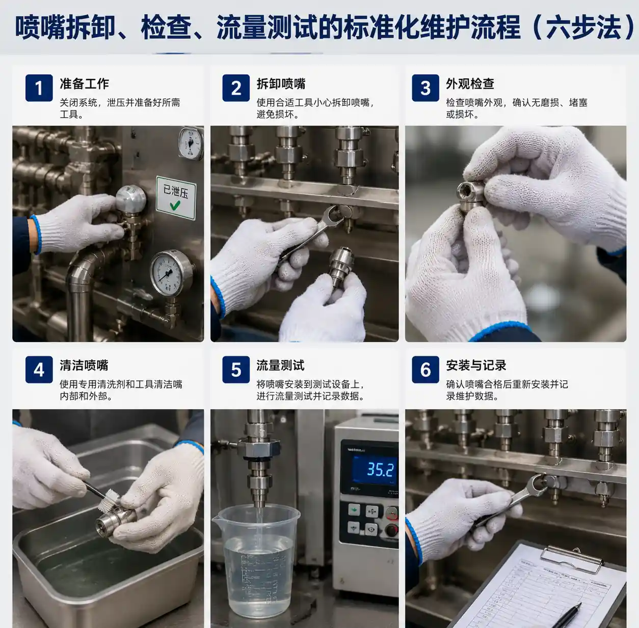
7.1 Bucket-and-Stopwatch Flow Test
Procedure: At constant system pressure (use pressure gauge at manifold), capture full nozzle flow in a graduated container for 60 seconds. Compare to baseline flow rate (from manufacturer data sheet or commissioning tests).
Acceptance criteria: Flow within ±10% of baseline indicates normal operation. Flow reduction of 10–20% suggests partial clogging; >20% requires immediate cleaning or replacement.
Field tip: Test at 3–4 representative pressures (50%, 75%, 100% of operating pressure) to generate a flow-vs-pressure curve. Clogged nozzles show reduced slope.
7.2 Spray Pattern Visualization
Method 1 (Water-sensitive paper): Spray onto yellow water-sensitive paper positioned perpendicular to spray axis at the design impact distance. Blue dots indicate droplet impacts. Uniform coverage confirms proper operation; bare spots or streaking indicate partial blockage.
Method 2 (Backlit observation): Position nozzle against dark background with strong backlighting. Observe spray cone symmetry and boundary sharpness. Partial blockage creates asymmetry or feathering at cone edges.
7.3 Pressure Drop Monitoring
Install pressure gauges immediately upstream and downstream of nozzle manifolds. Gradual increase in manifold pressure (with flow rate constant) indicates cumulative clogging of multiple nozzles reducing system capacity.
Diagnostic logic:
- Pressure increases + individual nozzle flow decreases = partial clogging.
- Pressure constant + individual nozzle flow decreases = nozzle wear or erosion (different failure mode).
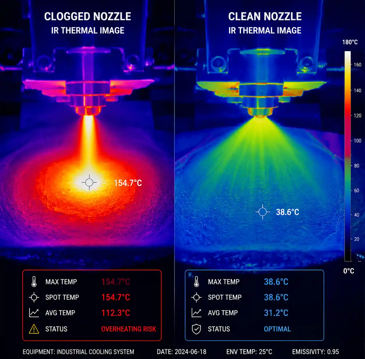
7.4 Thermal Imaging (for Cooling Applications)
Use IR camera to map temperature of surfaces being cooled. Hot spots indicate inadequate spray coverage from clogged nozzles. This non-contact method allows diagnosis without system shutdown.
8. Material Selection for Clog-Resistant Performance
Nozzle material affects clogging susceptibility through three mechanisms: erosion resistance (maintains designed orifice size), corrosion resistance (prevents internal roughness that traps particles), and surface finish (smoother surfaces resist scaling and biofilm attachment).
8.1 Material Comparison for Clog Resistance
Brass (360 alloy): Economical, good corrosion resistance in clean water. Erosion resistance poor with abrasive fluids (relative wear rate: 1.0x baseline). Use for clean water applications below 100 psi.
Stainless steel (303, 316): Excellent corrosion resistance, moderate erosion resistance (relative wear rate: 0.3–0.5x brass). 316 preferred for chloride-containing fluids. Our field data shows 3–5x longer service life than brass in typical cooling water applications. Can be electropolished for superior surface finish (Ra < 0.4 microns) that resists scaling.
Ceramic (alumina, zirconia): Very high erosion resistance (relative wear rate: 0.05–0.10x brass), maintains orifice size in abrasive slurries. Drawback: brittle, susceptible to pressure spikes and thermal shock. Recommended for high-solids applications where wear is the dominant failure mode.
Silicon carbide or tungsten carbide: Maximum erosion resistance (relative wear rate: 0.02–0.05x brass), used in the most severe abrasive conditions (fly ash slurries, mining applications, coal gasification). Very expensive but pays off in ultra-long service intervals.
PTFE or PFA-lined: Used in highly corrosive chemical applications (concentrated acids, strong alkalis). Excellent chemical resistance but poor mechanical strength—requires robust support design. Smooth fluoropolymer surface resists scaling and biofilm adhesion.
Table 4: Material Selection Guide for Clog-Prone Applications
| Application Characteristic | Recommended Material | Second Choice | Avoid |
|---|---|---|---|
| Clean water, <150 psi | Stainless steel 316 | Brass | Ceramic (overkill, brittle) |
| Hard water, scaling tendency | Electropolished 316 SS | PTFE-lined | Rough-finished brass |
| Abrasive slurry (>1000 ppm solids) | Silicon carbide | Ceramic alumina | Brass, soft alloys |
| Corrosive chemicals (pH<3 or >11) | PFA/PTFE-lined | Exotic alloys (Hastelloy) | Brass, carbon steel |
| Biofilm-prone (recirculating organics) | Electropolished 316 SS | Brass (frequent cleaning) | Rough-finished materials |
| High-temperature (>200°C) | 316 SS or ceramic | 303 SS | Plastic, PTFE |
8.2 Surface Finish Impact
Ra (average surface roughness) dramatically affects fouling rates. Our comparative testing in hard water (250 ppm hardness, 70°C) showed:
- Rough-machined brass (Ra 1.6–3.2 microns): Heavy scaling within 200 hours.
- Standard machined 316 SS (Ra 0.8–1.6 microns): Moderate scaling within 500 hours.
- Electropolished 316 SS (Ra 0.2–0.4 microns): Minimal scaling after 2000+ hours.
Smoother surfaces offer fewer nucleation sites for scale crystals and make biofilm attachment more difficult. For applications with known scaling or biological challenges, specify electropolished or mechanically polished internals.
9. Frequently Asked Questions
Q: How often should I replace nozzles even if they're not clogged?
A: Replace based on wear criteria, not arbitrary time intervals. For hydraulic nozzles in clean-water applications, inspect every 2000–5000 operating hours. Replace when flow rate increases >10% (indicates wear enlarging the orifice) or spray angle narrows >5°. For abrasive or corrosive applications, shorten intervals to 500–1000 hours initially, then adjust based on observed wear rates. Keep 2–3 nozzles as "witness samples" that you measure frequently to predict when the bulk population will need replacement.
Q: Can I use compressed air to clear a clogged nozzle in place?
A: Reverse-flow air purging (150–200 psi) sometimes clears soft blockages (biofilm fragments, loose particulate) but rarely removes hard scale or jammed foreign objects. Risk: overpressure can damage internal components (swirl vanes, filter screens) or unseat sealing elements. Better approach: remove, inspect visually, clean properly. If you must attempt in-place clearing, limit air pressure to <100 psi and purge for only 2–3 seconds. If blockage doesn't clear immediately, remove the nozzle.
Q: My nozzles keep clogging despite 100-mesh strainers. What's wrong?
A: Several possibilities: (1) Strainers are installed but not serviced regularly—check differential pressure and clean; (2) Particles deform and pass through mesh when wet, then expand inside nozzle orifices; (3) You have chemical scaling or biological growth, not particulate clogging—requires different remediation; (4) Orifice size is too small for 100-mesh—switch to 200 mesh or finer; (5) Contamination introduced downstream of strainers (dead legs, corrosion in manifold piping). Perform root cause analysis: disassemble clogged nozzle and analyze debris type before investing in filtration upgrades.
Q: Is ultrasonic cleaning better than acid cleaning for removing scale?
A: Each method works best for different deposits. Ultrasonic cleaning (frequency 35–50 kHz, cleaning solution appropriate to deposit type, 15–30 minutes) excels at removing particulate buildup, biofilms, and soft organic deposits. It's gentle on nozzle internals. Acid cleaning (5–10% citric or hydrochloric acid, 30–60 minutes soak with agitation) is required for hard mineral scale (calcium carbonate, iron oxides). For mixed fouling, sequence them: ultrasonic first to remove loose debris, then acid to dissolve hard scale, then ultrasonic rinse to remove acid and dissolved salts. Always flush thoroughly with clean water and dry before reinstallation.
Q: Can I mix nozzle brands or types in the same manifold?
A: Not recommended if you need uniform coverage or flow distribution. Different manufacturers' flow coefficients vary ±5–15% even at the same nominal capacity, and spray angles may differ by ±5–10°. This creates uneven coverage and makes troubleshooting difficult. Exception: If you're deliberately creating a non-uniform pattern (e.g., higher density at specific zones), mixing is acceptable but document the design clearly. For maintenance simplicity and spare parts inventory reduction, standardize on one manufacturer and minimize nozzle type variety.
Q: My system uses recirculated washwater—how aggressively should I filter it?
A: Depends on nozzle orifice size and soil loading. For wash systems with >2.0 mm orifices and moderate soil (metal chips, machining oils), a two-stage approach works well: coarse strainer (20–40 mesh) after the tank to catch heavy debris, then fine strainer (80–100 mesh) immediately before nozzle manifolds. If soil loading is high (grinding operations, heavy rust), add a settling tank or cyclone separator before the first filter stage to reduce filter cleaning frequency. Monitor filter differential pressure and clean or replace elements when ΔP reaches 10 psi. For orifices <1.5 mm, consider bag filters or cartridge filters rated to 50–75 microns.
10. Conclusion and Next Actions
Nozzle clogging is not a random event—it follows predictable patterns determined by fluid properties, system design, and operating conditions. By systematically addressing the five root causes (particulate contamination, chemical precipitation, biological growth, fluid incompatibility, and foreign object intrusion), you can achieve 80–90% reduction in clogging incidents while extending nozzle service life by 2–4x.
Next steps to optimize your spray system:
- Conduct a clogging root cause analysis on your three most problematic applications using the diagnostic methods in Section 7.
- Audit your current filtration against the sizing rules in Section 3; upgrade where gaps exist.
- Implement the application-specific preventive maintenance checklist from Section 6 for your highest-risk systems.
- If you're experiencing persistent clogging despite following these guidelines, request a field application audit—experienced spray engineers can often identify non-obvious causes (flow stagnation zones, localized corrosion, thermal cycling effects) that aren't apparent from remote diagnosis.
Industrial nozzle systems are critical to process performance, quality, and efficiency. The preventive approach outlined here—combining proper design, systematic maintenance, and data-driven decision-making—transforms nozzles from a chronic maintenance headache into a reliable, predictable component of your operation.