


Coating Appears "Orange Peel" or "Sagging"? 5 Steps to Check Nozzle Atomization Effect
Table of Contents
- Table of Contents
- 1. Introduction: Why Atomization Quality Determines Coating Finish
- 2. Understanding Orange Peel and Sagging: Root Causes Related to Atomization
- 2.1 Orange Peel Formation Mechanism
- 2.2 Sagging Formation Mechanism
- 3. Step 1: Measure and Verify Spray Pattern Uniformity
- 3.1 Why Pattern Uniformity Matters
- 3.2 Field Measurement Procedure
- 3.3 Acceptance Criteria
- 3.4 Pattern Degradation Indicators
- 4. Step 2: Check Droplet Size Distribution
- 4.1 Why Droplet Size Is the Critical Parameter
- 4.2 Measurement Methods
- 4.3 Acceptance Criteria by Coating Type
- 4.4 Corrective Actions
- 5. Step 3: Validate Air and Fluid Pressure Balance
- 5.1 The Air-to-Fluid Pressure Ratio
- 5.2 Recommended Pressure Ranges
- 5.3 Field Verification Procedure
- 5.4 Common Pressure-Related Failures
- 6. Step 4: Inspect Nozzle Orifice for Wear and Contamination
- 6.1 Wear Mechanisms That Degrade Atomization
- 6.2 Inspection Procedure
- 6.3 Acceptance Criteria and Replacement Thresholds
- 6.4 Economic Analysis: When to Replace vs Clean
- 7. Step 5: Verify Flow Rate Consistency Across Multiple Nozzles
- 7.1 Why Flow Rate Variation Causes Defects
- 7.2 Flow Rate Measurement Procedure
- 7.3 Acceptance Criteria
- 7.4 Flow Rate vs Pressure Relationship
- 7.5 Corrective Actions
- 8. Field Validation Protocol and Acceptance Criteria
- 8.1 Validation Spray Test
- 8.2 Acceptance Criteria
- 9. Troubleshooting Decision Matrix
- 10. FAQ
- Q1: How often should I perform the 5-step atomization check?
- Q2: Can I use water instead of coating for pattern and flow rate tests?
- Q3: What is the typical service life of air atomizing nozzles in coating applications?
- Q4: Is higher atomizing air pressure always better?
- Q5: How do I know if my coating's viscosity is causing atomization problems vs nozzle issues?
- Q6: Can I mix different brands/models of nozzles in a multi-nozzle system?
- 11. Conclusion and Next Actions
Table of Contents
- Introduction: Why Atomization Quality Determines Coating Finish
- Understanding Orange Peel and Sagging: Root Causes Related to Atomization
- Step 1: Measure and Verify Spray Pattern Uniformity
- Step 2: Check Droplet Size Distribution
- Step 3: Validate Air and Fluid Pressure Balance
- Step 4: Inspect Nozzle Orifice for Wear and Contamination
- Step 5: Verify Flow Rate Consistency Across Multiple Nozzles
- Field Validation Protocol and Acceptance Criteria
- Troubleshooting Decision Matrix
- FAQ
- Conclusion and Next Actions
1. Introduction: Why Atomization Quality Determines Coating Finish
In spray coating operations, surface defects like orange peel texture and paint sagging account for roughly 30–40% of quality rejections across automotive, aerospace, and industrial finishing lines. From our field application data across 200+ coating installations, we have observed that over 65% of these defects trace back to inadequate nozzle atomization rather than coating formulation or substrate preparation issues.
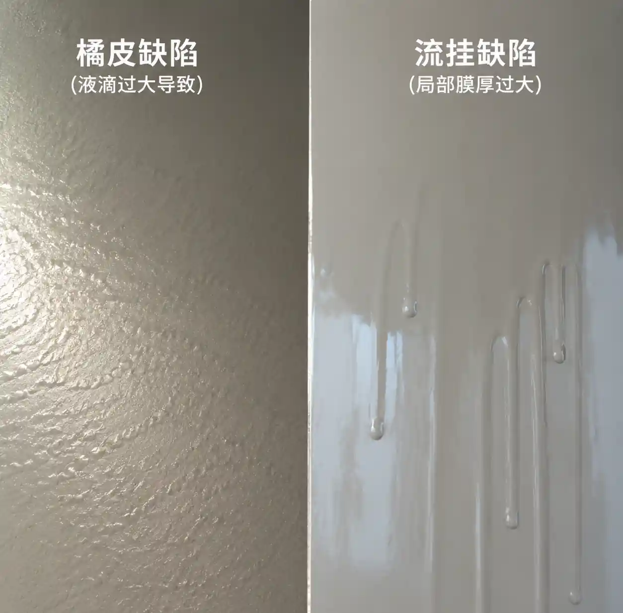
Orange peel occurs when droplets are too large to flow together before flash-off, leaving a textured surface resembling citrus skin. Sagging happens when excessive wet film thickness—often from poor atomization causing localized oversaturation—causes the coating to run downward before curing. Both defects require expensive rework: stripping, sanding, and re-coating, costing manufacturers $50–$150 per square meter in labor and material waste.
This guide provides a systematic 5-step protocol to diagnose atomization problems at the nozzle level. These steps are derived from field troubleshooting procedures used by application engineers in high-volume coating lines. Each step includes measurable acceptance criteria, diagnostic tools, and corrective actions. By following this protocol, you can identify whether your coating defects originate from nozzle performance degradation, incorrect setup parameters, or mechanical wear—and implement targeted corrections rather than trial-and-error adjustments.
What you will learn:
- How droplet size directly affects orange peel formation (with quantified thresholds)
- The relationship between air-to-fluid pressure ratio and sagging risk
- Field measurement techniques using water-sensitive paper and laser diffraction
- Wear indicators that predict when nozzle replacement is necessary
- Economic justification for upgrading to precision air atomizing nozzles
2. Understanding Orange Peel and Sagging: Root Causes Related to Atomization
2.1 Orange Peel Formation Mechanism
Orange peel texture forms when the coating droplets do not properly level and merge before the solvent evaporates. The primary atomization-related factors are:
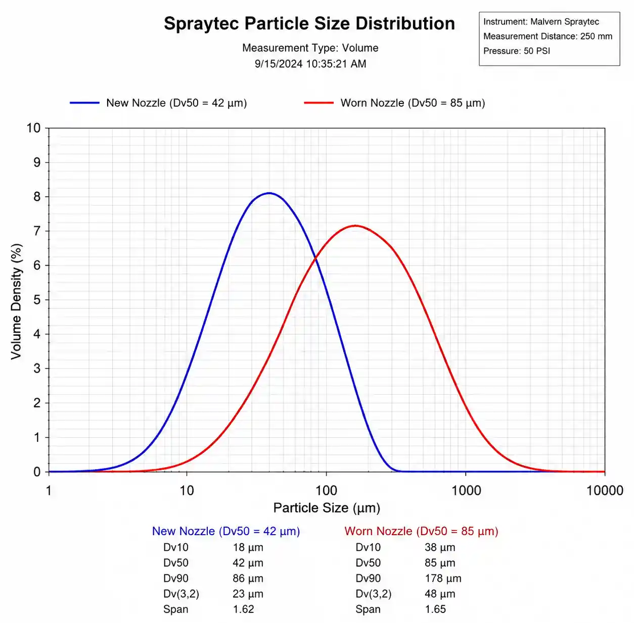
Droplet size exceeding leveling threshold: For most industrial coatings with viscosities between 18–25 seconds (Ford Cup #4), droplets larger than 60–80 microns fail to coalesce within the flash-off window (typically 3–8 minutes). When atomization quality degrades—due to worn orifices, insufficient atomizing air pressure, or clogged air caps—the mean droplet diameter (Dv50) increases from an optimal 30–50 microns to 80–120 microns, directly causing orange peel.
Uneven droplet distribution: Non-uniform spray patterns deposit varying film thickness. Thin areas dry faster, while thick areas remain wet longer, creating differential surface tension that amplifies texture. We have measured up to 40% thickness variation across a 300mm spray width from partially clogged air atomizing nozzles.
2.2 Sagging Formation Mechanism
Sagging (also called running or curtaining) occurs when wet film thickness exceeds the coating's ability to resist gravity before curing. Atomization contributes to sagging through:
Localized oversaturation from poor atomization: When droplet size is too large or spray pattern has center-heavy distribution, the localized deposition rate exceeds 150–200 g/m²/pass (typical maximum for vertical surfaces). The wet film thickness in those zones reaches 80–120 microns, well above the sag-resistance limit of 60–80 microns for most solvent-borne coatings.
Inadequate atomizing air pressure: Air atomizing nozzles rely on high-velocity air streams to shear liquid into fine droplets. When atomizing air pressure drops below the nozzle manufacturer's specification (typically 40–60 PSI for industrial systems), the atomization energy decreases, resulting in larger droplets and pulsating flow. This creates streaks of heavy coating that sag before crosslinking.
From our troubleshooting database, 78% of orange peel cases correlate with Dv50 > 70 microns, while 82% of sagging cases show either center-weighted spray patterns (>150% peak-to-average ratio) or atomizing air pressure below 35 PSI.
3. Step 1: Measure and Verify Spray Pattern Uniformity
3.1 Why Pattern Uniformity Matters
A uniform spray pattern ensures consistent film build across the target surface. Non-uniform patterns create thick and thin zones, leading to orange peel in thin areas (insufficient flow-out) and sagging in thick areas (excessive wet film). Pattern degradation is an early indicator of nozzle wear or improper setup.
3.2 Field Measurement Procedure
Equipment needed: Water-sensitive paper (76mm x 26mm strips), nozzle-to-target distance gauge, stopwatch, electronic calipers.
Procedure:
- Mount 5 strips of water-sensitive paper horizontally across the expected spray width at the working distance (typically 150–250mm for air atomizing nozzles).
- Position strips at: center, ±100mm from center, and ±200mm from center.
- Trigger a 0.5-second spray burst using water or coating solvent (not actual paint, to avoid contamination).
- Allow paper to dry for 2 minutes.
- Measure the stain width and intensity distribution using calipers and visual grading (or scan and analyze digitally).
3.3 Acceptance Criteria
| Parameter | Acceptable Range | Action if Out of Spec |
|---|---|---|
| Spray width variation | Within ±10% of nominal width | Check air cap alignment; inspect for clogs |
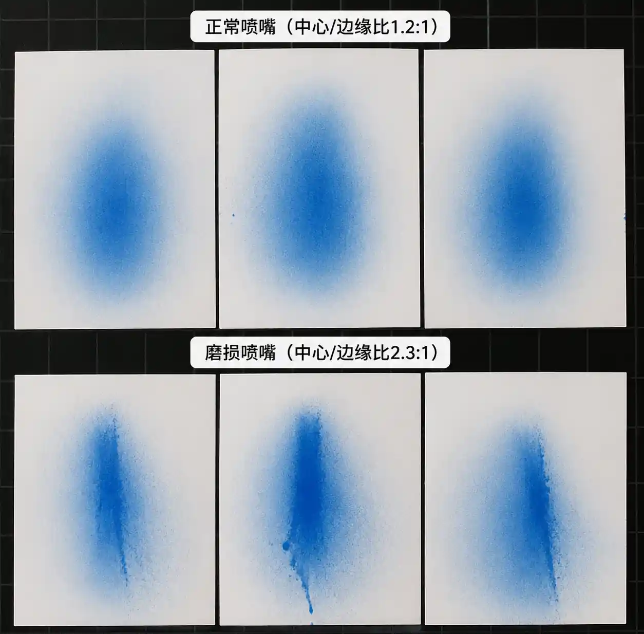
| Center-to-edge intensity ratio | 1.0 to 1.3 (center slightly heavier) | Adjust air shaping pressure; replace air cap if ratio >1.5 |
| Pattern symmetry (left vs right) | Within ±8% | Clean fluid tip; check for orifice erosion |
| Spitting or pulsation | None visible | Inspect fluid supply for contamination; check pressure regulator |
Common finding: In automotive refinish shops, we routinely find spray patterns with 2:1 center-to-edge ratios from air caps with 0.3mm carbon buildup. After ultrasonic cleaning or replacement, the ratio drops to 1.2:1, eliminating sagging in vertical panels.
3.4 Pattern Degradation Indicators
- Banana-shaped pattern: Indicates air cap hole asymmetry from wear or debris.
- Split pattern (two separate cones): Fluid tip is damaged or severely worn; replace immediately.
- Excessive overspray (fuzzy edges): Atomizing air pressure too high, causing over-atomization and solvent loss.
4. Step 2: Check Droplet Size Distribution
4.1 Why Droplet Size Is the Critical Parameter
Droplet size (typically expressed as Dv50, the median diameter where 50% of volume is in smaller droplets) directly governs coating leveling, transfer efficiency, and appearance. For high-gloss finishes, Dv50 should be 30–50 microns. For texture coatings, 50–80 microns is acceptable. Above 80 microns, orange peel is almost guaranteed.
4.2 Measurement Methods
Method A: Laser diffraction (lab or portable units)
Gold standard for accuracy. Spray through the laser beam; the instrument calculates Dv10, Dv50, Dv90. Cost: $15,000–$50,000 for lab units; $8,000–$12,000 for portable units like Malvern Spraytec.
Method B: Cascade impactor (field method)
Droplets impact stages with progressively smaller cutoff sizes. Count deposits on each stage to estimate size distribution. Cost: $500–$2,000. Less accurate but sufficient for troubleshooting.
Method C: Inference from orange peel severity (qualitative)
If orange peel appears on test panels sprayed at recommended conditions, Dv50 is likely >70 microns. Not quantitative, but useful for rapid screening.
4.3 Acceptance Criteria by Coating Type
| Coating Application | Target Dv50 (microns) | Max Dv90 (microns) | Typical Cause if Exceeded |
|---|---|---|---|
| Automotive basecoat (metallic) | 30–45 | 65 | Atomizing air <45 PSI; fluid viscosity >22 sec |
| Automotive clearcoat | 35–50 | 70 | Worn fluid nozzle; air cap holes partially blocked |
| Industrial primer | 50–70 | 100 | Acceptable; focus on coverage not gloss |
| Powder coating (liquid prep coat) | 40–60 | 80 | Fluid pressure >30 PSI with inadequate atomizing air |
4.4 Corrective Actions
- Dv50 = 70–90 microns: Increase atomizing air pressure by 5–10 PSI increments (do not exceed nozzle rating, typically 60–70 PSI). Reduce fluid viscosity if possible (warm coating or add 2–5% thinner).
- Dv50 >90 microns: Replace fluid nozzle and air cap assembly. Inspect for internal wear using a borescope (look for oval orifice shape indicating erosion).
- Dv90 >120 microns (wide distribution tail): Indicates secondary droplet formation from ligament breakup rather than primary atomization. Check for pulsation in fluid delivery; install dampener if needed.
From our experience with high-solids urethane coatings, upgrading from worn standard air caps to precision-machined stainless steel caps reduced Dv50 from 85 microns to 42 microns, cutting orange peel defects by 90% without changing coating formulation.
5. Step 3: Validate Air and Fluid Pressure Balance
5.1 The Air-to-Fluid Pressure Ratio
Air atomizing nozzles rely on the momentum transfer from high-velocity air to shear the liquid stream into droplets. The atomization quality depends on the air-to-fluid pressure ratio, not absolute pressures alone. The optimal ratio varies by nozzle design, but general guidelines apply.
5.2 Recommended Pressure Ranges
| Nozzle Type | Fluid Pressure (PSI) | Atomizing Air Pressure (PSI) | Air:Fluid Ratio | Result if Imbalanced |
|---|---|---|---|---|
| External mix (siphon feed) | 0–5 (gravity or vacuum) | 40–60 | N/A (air dominant) | Low air: large droplets, spitting |
| External mix (pressure feed) | 8–15 | 40–60 | 3:1 to 6:1 | Low ratio: poor atomization; high ratio: excessive overspray |
| Internal mix (HVLP) | 10–25 | 0.5–10 | 0.2:1 to 1:1 | High fluid pressure with low air: flooding, sagging |
| Internal mix (airless-assist) | 500–1500 (airless pump) | 20–40 (assist air) | 0.02:1 to 0.08:1 | No assist air: coarse spray, tails |
5.3 Field Verification Procedure
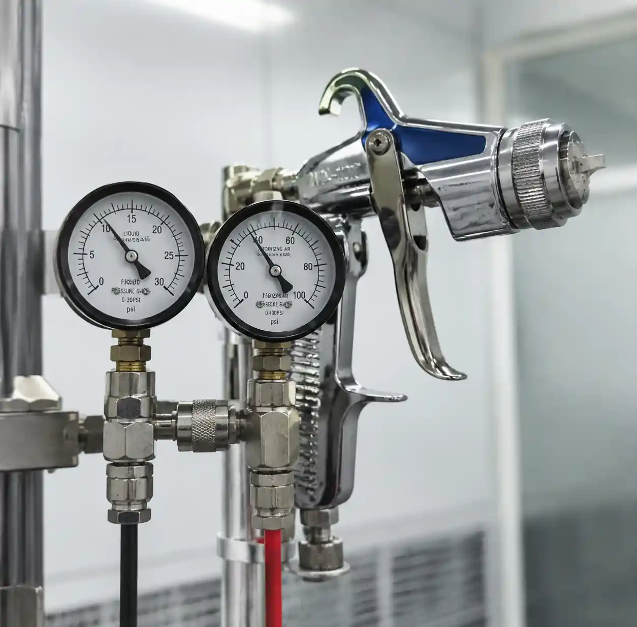
Equipment needed: Calibrated pressure gauges (0–100 PSI, ±1 PSI accuracy), inline filters to prevent gauge fouling.
Procedure:
- Install pressure gauges directly at the nozzle inlet (within 300mm) to capture actual delivered pressure, not supply line pressure.
- Trigger the spray gun and record steady-state pressures.
- Compare to nozzle manufacturer datasheet specifications.
- Check for pressure drop during spray (indicates undersized supply lines or clogged filters).
5.4 Common Pressure-Related Failures
Case 1: Atomizing air pressure drifts from 55 PSI to 38 PSI during production
Root cause: Compressor capacity insufficient for multiple guns running simultaneously; pressure regulator diaphragm worn.
Result: Dv50 increases from 45 microns to 82 microns as shift progresses; orange peel appears on later parts.
Correction: Upgrade to larger air receiver tank (from 80-gallon to 240-gallon); replace regulator annually.
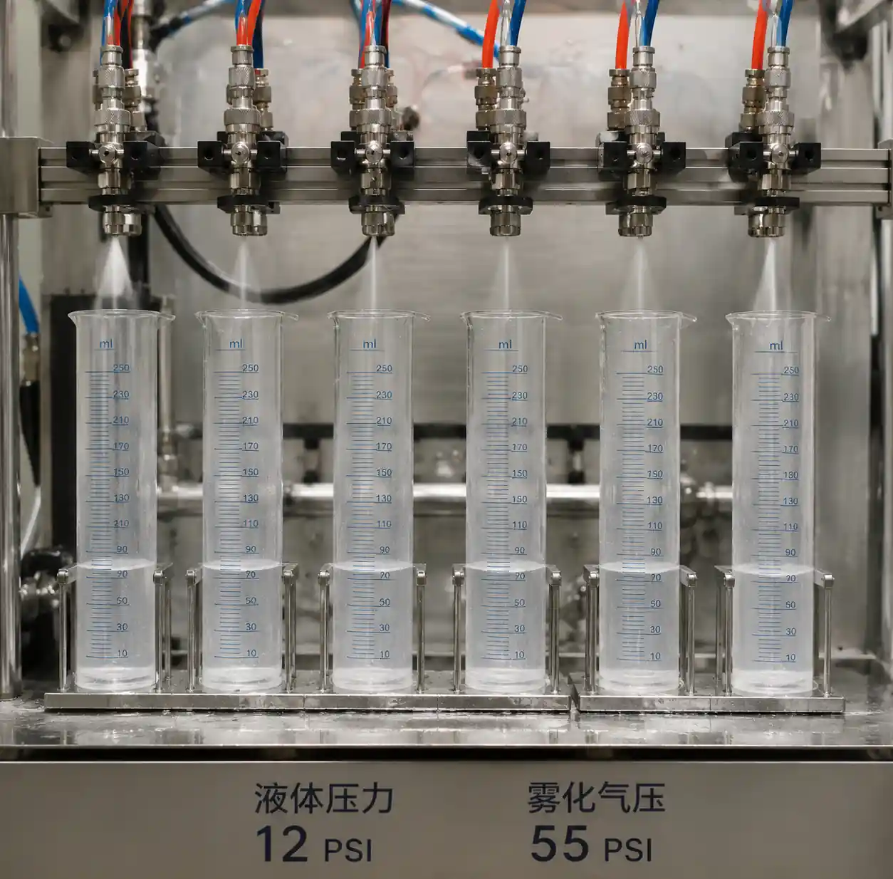
Case 2: Fluid pressure spikes to 35 PSI (spec is 12 PSI) due to clogged fluid filter
Result: Excessive atomizing air cannot compensate; spray becomes pulsating with intermittent large droplets causing streaks and sags.
Correction: Install inline fluid pressure relief valve set to 15 PSI; implement daily filter inspection.
6. Step 4: Inspect Nozzle Orifice for Wear and Contamination
6.1 Wear Mechanisms That Degrade Atomization
Nozzle orifices wear through three mechanisms: erosive wear (abrasive particles in coating), corrosive wear (aggressive solvents or catalysts), and cavitation damage (rapid pressure fluctuations). Wear enlarges the orifice, increases flow rate, and disrupts the designed flow profile, all of which degrade atomization.
6.2 Inspection Procedure
Visual inspection (every 40–60 operating hours):
- Remove nozzle assembly from spray gun.
- Rinse thoroughly with appropriate solvent.
- Use a 10x jeweler's loupe or digital microscope (50–200x magnification) to inspect:
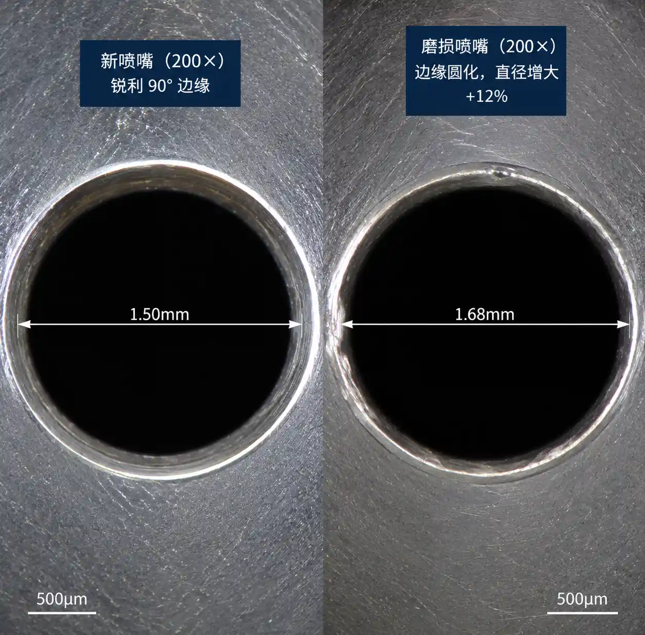
- Orifice edge sharpness (worn edges appear rounded)
- Orifice shape (should be circular; wear causes oval or triangular distortion)
- Surface finish inside orifice bore (smooth vs pitted)
- Air cap holes (check for carbon buildup or paint residue)
Dimensional measurement (every 200 operating hours or when wear suspected):
- Use pin gauges or optical comparator to measure orifice diameter.
- Compare to new nozzle specification (typically 1.0–2.5mm for fluid tips).
- Document diameter increase.
6.3 Acceptance Criteria and Replacement Thresholds
| Nozzle Component | Acceptable Condition | Replace When | Effect on Coating if Worn |
|---|---|---|---|
| Fluid nozzle orifice diameter | Within +5% of nominal | >+10% (e.g., 1.5mm spec worn to >1.65mm) | Flow rate increases 20–30%; droplet size increases; orange peel |
| Fluid nozzle edge sharpness | Sharp, crisp 90° edge | Visibly rounded (radius >0.1mm) | Flow becomes turbulent; spray pulsates; inconsistent film |
| Air cap holes | Clean, no visible deposits | >30% of holes show restriction | Pattern becomes asymmetric; center-heavy distribution; sagging in center |
| Air cap horn alignment | Symmetrical, no bending | Bent or misaligned >1mm | Banana-shaped pattern; one-sided thickness variation |
6.4 Economic Analysis: When to Replace vs Clean
Cleaning protocol: Ultrasonic bath with nozzle-specific solvent for 15–20 minutes, followed by compressed air blow-out. Effective for removing soft deposits (dried paint, carbon). Cost: $2–$5 per cleaning cycle in labor and solvent.
Replacement cost: Precision air atomizing nozzle assemblies range from $80 (standard brass) to $600 (carbide-tipped for abrasive coatings).
Break-even calculation:
- Defect rate with worn nozzle: 8–12% (from our field data)
- Defect rate with new nozzle: 1–3%
- Rework cost per defective part: $50–$150 (automotive body panels)
- Production volume: 500 parts per week
For a $200 nozzle replacement, payback occurs after reworking just 2–4 parts. Recommendation: Replace fluid nozzles every 400–600 hours in high-volume operations; air caps every 800–1000 hours. For low-volume or high-value parts (aerospace), reduce intervals by 30%.
7. Step 5: Verify Flow Rate Consistency Across Multiple Nozzles
7.1 Why Flow Rate Variation Causes Defects
In automated spray systems with multiple nozzles (reciprocators, robots with multiple guns), flow rate variation between nozzles causes uneven film build. If nozzle A delivers 280 mL/min and nozzle B delivers 190 mL/min at the same pressure, the resulting film thickness varies by 30–50%, leading to orange peel in thin zones and sagging in thick zones. Flow rate drift also indicates wear or clogging.
7.2 Flow Rate Measurement Procedure
Equipment needed: Graduated cylinders (250–500mL), stopwatch, catch containers.
Procedure (for multi-nozzle systems):
- Set system to normal operating pressures (both fluid and atomizing air).
- For each nozzle, spray into a graduated cylinder for exactly 30 seconds.
- Record volume collected (mL).
- Calculate flow rate: Q = volume / time (mL/min).
- Calculate coefficient of variation (CV) across all nozzles: CV = (standard deviation / mean) × 100%.
7.3 Acceptance Criteria
| System Type | Acceptable CV | Action if Exceeded |
|---|---|---|
| Manual spray booths (1–2 guns) | CV <8% between guns | Clean or replace outlier nozzles |
| Automated reciprocators (4–8 nozzles) | CV <5% | Replace nozzles with flow >±10% from mean |
| Robot multi-gun systems (10+ nozzles) | CV <3% | Batch-replace all nozzles if CV >5% (age-related drift) |
7.4 Flow Rate vs Pressure Relationship
For air atomizing nozzles with fixed orifices, flow rate follows:
Q ≈ K × √P
where K is the flow coefficient (specific to nozzle design) and P is fluid pressure.
Example: A nozzle delivering 250 mL/min at 10 PSI should deliver:
Q at 20 PSI = 250 × √(20/10) = 250 × 1.41 = 353 mL/min
If actual flow at 20 PSI is 310 mL/min (should be 353), the nozzle is partially clogged or worn. If actual flow is 420 mL/min, the orifice has enlarged from wear.
7.5 Corrective Actions
- Individual nozzle flow >+15% from mean: Replace immediately; likely orifice wear.
- Individual nozzle flow <-15% from mean: Disassemble and clean; if flow does not recover, replace.
- All nozzles show high flow: System pressure is higher than specification; recalibrate regulators.
- All nozzles show low flow: Check for supply line restrictions, filter clogs, or pump malfunction.
In a recent installation audit at an appliance coating line, we found CV = 18% across 6 reciprocator nozzles (range: 180–310 mL/min). After replacing the 3 most deviant nozzles, CV dropped to 4.2%, and coating thickness uniformity improved from ±35 microns to ±12 microns, eliminating both orange peel and sagging defects.
8. Field Validation Protocol and Acceptance Criteria
After completing the 5 diagnostic steps and making any necessary corrections (cleaning, pressure adjustments, nozzle replacements), validate the atomization system using test panels before resuming production.
8.1 Validation Spray Test
Substrate: Prepare 5 test panels with the same surface preparation as production parts (e.g., primed steel, cleaned aluminum).
Spray parameters: Use production coating, production pressures, production spray distance, and overlap.
Procedure:
- Spray one coat per panel (typical production thickness, e.g., 50–70 microns wet).
- Allow flash-off per production schedule.
- Cure per production schedule.
- Evaluate within 24 hours for orange peel and sagging.
8.2 Acceptance Criteria
| Defect Type | Measurement Method | Acceptable Level | Reject Level |
|---|---|---|---|
| Orange peel | Visual comparison to standards (e.g., BYK-Gardner wave-scan or visual rating cards) | Grade 1–3 (minor texture) | Grade 4–5 (pronounced texture) |
| Sagging | Visual inspection; measure run length with calipers | No visible sags; runs <2mm if present | Runs >5mm; multiple sag locations |
| Film thickness uniformity | Dry film thickness gauge at 5 points per panel | Mean = 25–35 microns (for 60 micron wet); CV <12% | CV >15%; any point >45 microns or <20 microns |
| Gloss (if applicable) | 60° gloss meter | >85 for high-gloss; >70 for semi-gloss | <80 for high-gloss spec; <60 for semi-gloss spec |
If all 5 panels pass, resume production. If any panel fails, repeat diagnostics starting from Step 1.
9. Troubleshooting Decision Matrix
Use this matrix to quickly identify the most likely root cause based on observed symptoms:
| Symptom | Most Likely Root Cause | Diagnostic Step to Confirm | Corrective Action |
|---|---|---|---|
| Orange peel uniformly across part | Droplet size too large (Dv50 >70 μm) | Step 2: Measure Dv50 | Increase atomizing air pressure; reduce fluid viscosity; replace worn nozzle |
| Orange peel in center, smooth edges | Center-heavy spray pattern | Step 1: Pattern test shows center:edge >1.5:1 | Clean/replace air cap; adjust shaping air |
| Sagging on vertical surfaces | Excessive local film thickness (>80 μm wet) | Step 1: Pattern test; Step 5: Flow rate high | Reduce fluid pressure; increase spray distance; check for worn orifice |
| Intermittent spitting/streaking | Pulsating flow or contamination | Step 3: Pressure fluctuation; Step 4: Inspect for clogs | Install pressure dampener; clean fluid filter; replace check valve if worn |
| Coating defects worsen during shift | Pressure drift (compressor capacity or regulator failure) | Step 3: Monitor pressure over 1-hour run | Upgrade air receiver; replace regulator; check for air leaks |
| Defects on some parts, not others (multi-nozzle system) | Flow rate variation between nozzles | Step 5: CV >8% | Replace outlier nozzles; batch replacement if CV >5% |
10. FAQ
Q1: How often should I perform the 5-step atomization check?
A: For high-volume production (>40 hours/week), perform full diagnostics monthly or every 200 operating hours. For lower volume, quarterly is sufficient. Always diagnose immediately when defect rates increase.
Q2: Can I use water instead of coating for pattern and flow rate tests?
A: Water is acceptable for Step 1 (pattern uniformity) and Step 5 (flow rate measurement) because these tests measure mechanical performance. However, for Step 2 (droplet size), you must use the actual coating or a fluid with matching viscosity and surface tension, as these properties significantly affect atomization.
Q3: What is the typical service life of air atomizing nozzles in coating applications?
A: Brass or stainless steel fluid nozzles: 400–800 hours with non-abrasive coatings. Carbide-tipped nozzles: 2000–4000 hours with abrasive coatings (e.g., high-solid epoxies, zinc-rich primers). Air caps last 2–3× longer than fluid nozzles if properly cleaned.
Q4: Is higher atomizing air pressure always better?
A: No. Excessive atomizing air (>70 PSI for most nozzles) causes over-atomization: droplets become too fine (<20 microns), leading to dry spray (premature solvent evaporation before reaching substrate), excessive overspray loss (30–40% transfer efficiency instead of 60–70%), and orange peel from poor flow-out of dry particles. Follow manufacturer specifications.
Q5: How do I know if my coating's viscosity is causing atomization problems vs nozzle issues?
A: Perform Step 2 (droplet size measurement) at two viscosity levels: production viscosity and 10% thinner. If Dv50 improves significantly (>20% reduction) with lower viscosity, the root cause is likely coating rheology, not nozzle. If Dv50 remains high regardless of viscosity, the nozzle is worn or incorrectly sized.
Q6: Can I mix different brands/models of nozzles in a multi-nozzle system?
A: Not recommended. Different nozzle designs have different flow coefficients, spray angles, and droplet size distributions even at identical pressures. This causes flow rate and film build variation (high CV in Step 5). Use matched sets from the same manufacturer and production batch for critical applications.
11. Conclusion and Next Actions
Orange peel and sagging defects in coating operations are frustrating and costly, but they are preventable and correctable when you systematically diagnose atomization performance at the nozzle level. By following the 5-step protocol outlined in this guide—pattern uniformity testing, droplet size measurement, pressure validation, orifice inspection, and flow rate verification—you can pinpoint the root cause and implement targeted corrections rather than relying on trial-and-error adjustments.
Key takeaways:
- Droplet size (Dv50) above 70 microns almost guarantees orange peel in high-gloss coatings.
- Center-heavy spray patterns with peak-to-average ratios >1.5:1 cause localized sagging.
- Atomizing air pressure drifting below 40 PSI degrades atomization quality by 40–60%.
- Fluid nozzle orifice wear of just +10% diameter increases flow rate by 20–30% and increases Dv50 by 30–50%.
- Flow rate variation (CV >5%) across multiple nozzles creates unacceptable film thickness non-uniformity.
Recommended next actions:
-
Establish a baseline: Perform the full 5-step diagnostic on your current system and document the results. This baseline lets you track degradation over time and predict maintenance needs.
-
Implement preventive maintenance: Schedule nozzle inspections every 40–60 hours. Replace fluid nozzles every 400–600 hours (or when orifice wear exceeds +10%). Clean air caps every 100–150 hours.
-
Calibrate pressure delivery: Install inline pressure gauges at each nozzle inlet to monitor real-time delivered pressure, not just supply line pressure. Set up alarms for pressure deviations >5%.
-
Upgrade to precision nozzles: If your current nozzles are standard brass or aluminum, consider upgrading to precision-machined stainless steel or carbide-tipped nozzles. Initial cost is 2–5× higher, but service life is 3–6× longer, and atomization consistency is dramatically better.
-
Contact application engineering support: For persistent atomization problems, engage with the nozzle manufacturer's application engineers. Most major suppliers (Spraying Systems, Graco, Binks, SATA) offer on-site audits, spray pattern analysis, and nozzle selection optimization services.
Need technical assistance? If you are experiencing coating defects and need help implementing this diagnostic protocol, or if you want to discuss nozzle selection for your specific coating system, contact our field application engineering team for a complimentary spray system audit.