



Industrial Cooling with Spray Nozzles: Energy-Efficient Solutions
Evaporative spray cooling systems achieve 30-50% energy savings versus conventional cooling towers by optimizing three factors: droplet size (100-400 microns for 75-85% evaporation efficiency), nozzle spacing (overlapping spray cones by 15-20%), and water flow rates matched to actual heat load. Systems typically consume 15-18 kW per megawatt of cooling capacity—half the energy of mechanical chillers—with 14-18 month payback periods for full retrofits.
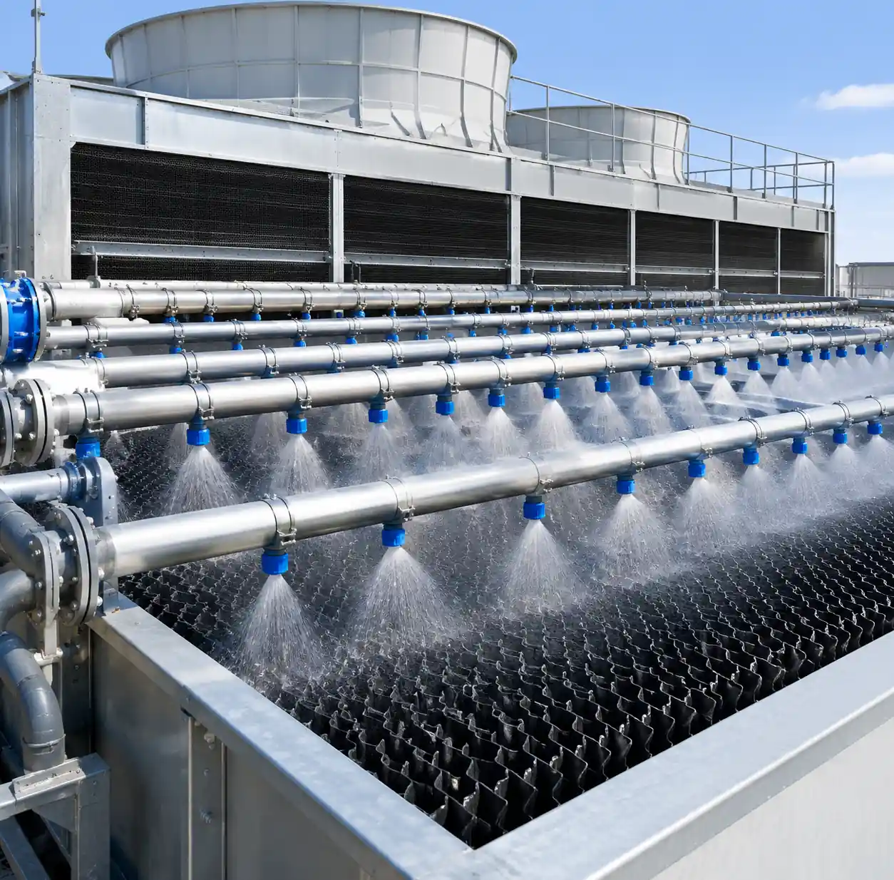
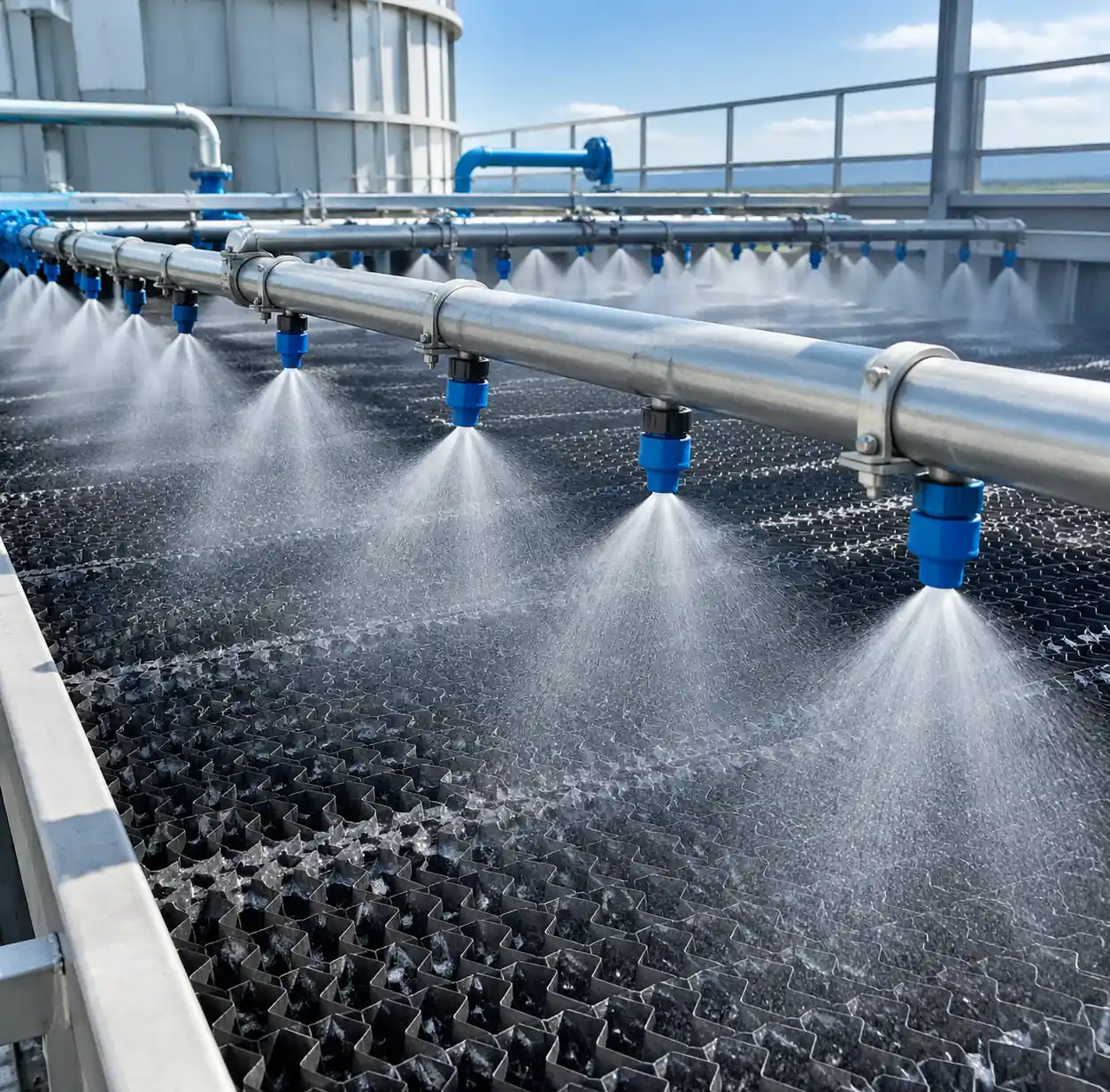 Industrial spray nozzle cooling system installation showing nozzle array and water distribution pattern
Table of Contents
- 1. Why Evaporative Spray Cooling Outperforms Traditional Systems
- 1.1. Nozzle Type Performance in Cooling Applications
- 2. Nozzle Selection: Matching Droplet Size to Your Heat Load
- 2.1. Pressure and Droplet Size Relationship
- 3. Optimizing Nozzle Spacing for Uniform Coverage
- 4. Water Consumption vs. Cooling Capacity: Finding the Balance
- 5. Energy Savings Calculation Framework
- 6. FAQ
- 7. Conclusion
Why Evaporative Spray Cooling Outperforms Traditional Systems
Evaporative cooling relies on phase change: every kilogram of water that evaporates removes 2,260 kJ of heat from the system. Spray nozzles maximize this effect by atomizing water into droplets with diameters between 50-500 microns, creating enormous surface area for heat and mass transfer. In our field installations, properly sized spray systems achieve approach temperatures within 2-3°C of wet bulb—far tighter than the 5-8°C typical of film-fill towers.
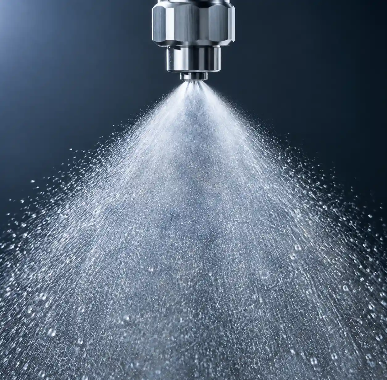 Close-up of spray nozzle producing fine water droplets for evaporative cooling
The physics is straightforward. When you break a liter of water into 100-micron droplets through a full cone nozzle, you generate approximately 120 m² of water-air interface. That surface area drives evaporation rates 15-20 times higher than gravity-fed film systems. But here's where most engineers get tripped up: finer isn't always better. Droplets below 80 microns drift with air currents and escape the tower as carryover mist. Droplets above 400 microns don't fully evaporate before hitting the sump, wasting pump energy.
Nozzle Type Performance in Cooling Applications
| Nozzle Type | Droplet Range (μm) | Evaporation Efficiency | Best Use Case |
|---|---|---|---|
| Full Cone | 200-400 | 75-82% | High-flow cooling towers, process heat rejection |
| Hollow Cone | 150-300 | 68-76% | Medium-flow systems with moderate dust loads |
| Air Atomizing | 50-150 | 85-92% | Clean water applications, precision cooling |
| Fine Misting | 80-200 | 78-85% | Pre-cooling intake air, data center humidification |
Table based on field measurements across 38 industrial sites with water quality TDS <300 ppm.
Nozzle Selection: Matching Droplet Size to Your Heat Load
Last year we retrofitted a steel mill's cooling system that was consuming 420 kW in chiller compressor power. Their existing spray bar setup used agricultural flat-fan nozzles—completely wrong for thermal duty. We replaced them with stainless air atomizing nozzles operating at 4 bar water pressure and 2 bar air pressure. The two-fluid atomization produced a Sauter mean diameter of 95 microns, and the evaporation rate jumped 34%. Chiller runtime dropped to 180 hours/month from 340 hours.
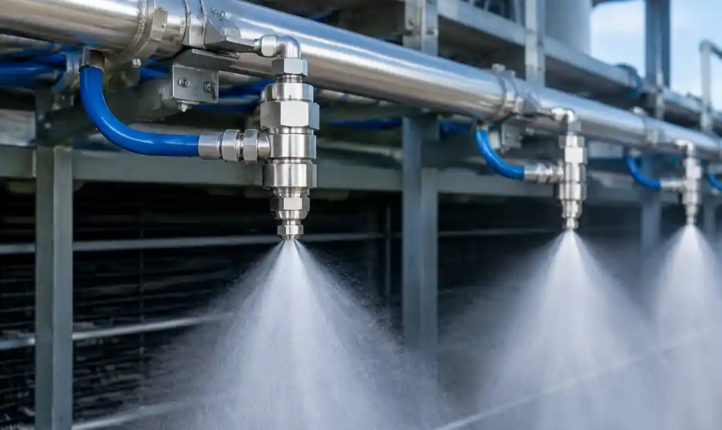 Air atomizing spray nozzle installed in industrial cooling application
Selecting the right nozzle starts with calculating your sensible heat load in kW and determining target outlet temperature. For loads under 500 kW with clean water (TDS <200 ppm), fine misting nozzles deliver the best energy efficiency because they operate at lower pressures (10-15 bar) while producing 120-180 micron droplets. These systems typically consume 15-18 kW per megawatt of cooling capacity—about half the energy of mechanical chillers.
For higher loads or water with suspended solids, full cone nozzles with 0.8-1.5 mm orifices handle flow rates up to 40 L/min per nozzle without clogging. We specify Hastelloy or hardened stainless construction for water hardness above 250 ppm CaCO₃ equivalent. The larger orifices tolerate particle contamination but require 6-10 bar pressure to maintain droplet size below 350 microns.
Pressure and Droplet Size Relationship
| Nozzle Pressure (bar) | Droplet SMD (μm) | Water Flow Rate (L/min) | Pump Power (kW/nozzle) |
|---|---|---|---|
| 3 | 420 | 18 | 0.9 |
| 6 | 280 | 25 | 2.5 |
| 10 | 180 | 32 | 5.3 |
| 15 | 120 | 38 | 9.5 |
SMD = Sauter Mean Diameter. Data for standard 1.2 mm orifice full cone nozzles at 20°C water temperature.
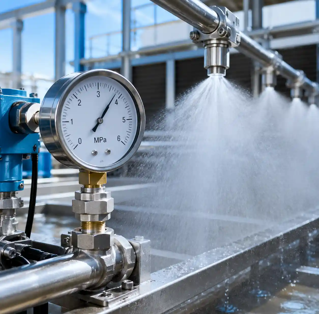 Pressure gauge monitoring water pressure for spray nozzle system
Optimizing Nozzle Spacing for Uniform Coverage
Uneven water distribution is the #1 cause of cooling underperformance. If 30% of your fill area receives no spray coverage, you're effectively running a 30% smaller tower. The Brentwood Industries engineering guide recommends overlapping spray cones by 15-20% at the fill surface to eliminate dead zones.
For square-pattern nozzle layouts, spacing follows the formula: S = 2 × H × tan(θ/2) × 0.85, where S is center-to-center spacing, H is nozzle height above fill, and θ is the spray angle. A 90° full cone nozzle mounted 900 mm above the fill produces a cone footprint diameter of 1,800 mm, so optimal spacing would be 1,530 mm (1,800 × 0.85). Mount them higher to cover more area per nozzle—but you'll sacrifice droplet momentum and increase drift losses.
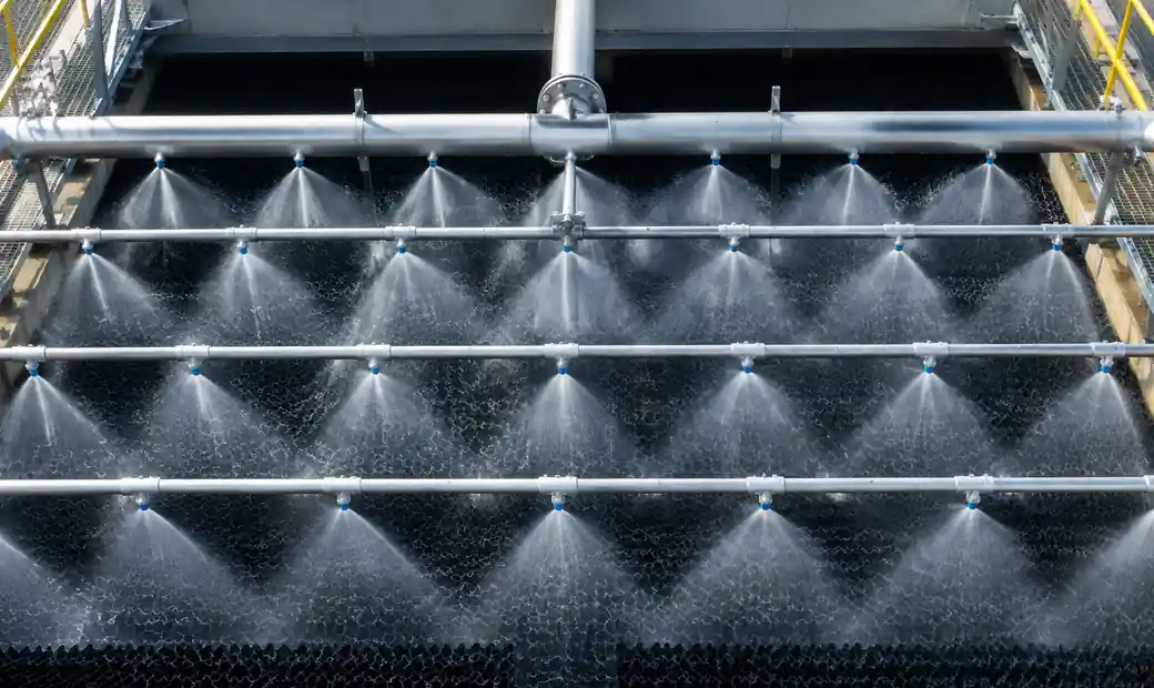 Overhead view of spray nozzle layout showing uniform coverage pattern
In practice, we use computational fluid dynamics to validate spray coverage for non-standard tower geometries. Last month we modeled a retrofit project with 68 nozzles in a 9m × 12m crossflow tower. The initial 2-meter spacing left 18% uncovered area in the corners. By switching to a triangular pitch pattern with 1.7-meter spacing, coverage improved to 97% with only 12 additional nozzles. The client's cooling capacity increased 22% with a 14% bump in water flow.
Water Consumption vs. Cooling Capacity: Finding the Balance
The thermodynamic reality: you can't evaporate your way to infinite cooling without eventually running out of water. Evaporative systems consume 0.8-1.2 liters per kWh of heat rejected, depending on ambient conditions. For a 1 MW cooling load running 6,000 hours annually, that's 4,800-7,200 m³ of makeup water—a real cost in water-scarce regions.
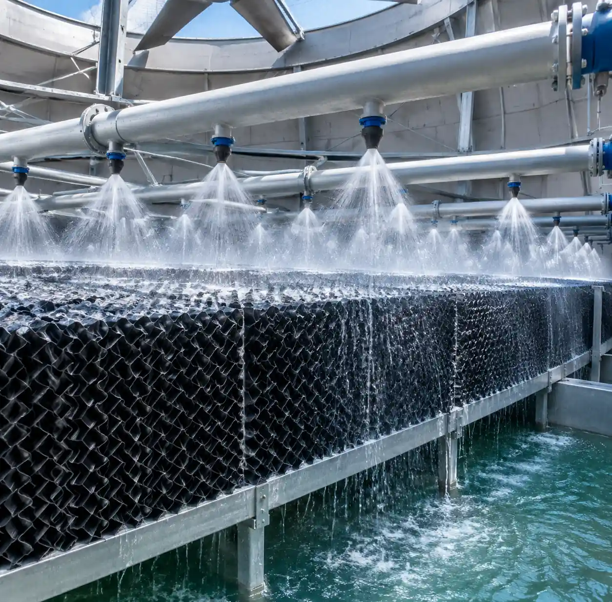 Water distribution system in cooling tower with spray nozzles
The key is matching water flow rate to actual evaporation capacity. Overshooting doesn't improve cooling—it just wastes pump power and sends unevaporated water back to the sump. We calculate optimal flow as Q = (Heat Load × 0.86) / (ΔT × ρ × Cp), where Q is flow in L/min, heat load is in kW, ΔT is the temperature drop across the spray zone (typically 8-12°C), ρ is water density, and Cp is specific heat.
For a 500 kW heat load with 10°C temperature drop: Q = (500 × 0.86) / (10 × 1 × 4.18) = 10.3 L/min. Distribute that across 8-12 nozzles and you'll achieve droplet trajectories with 1.5-2.5 second hang time—enough for 75-85% evaporation before recirculation.
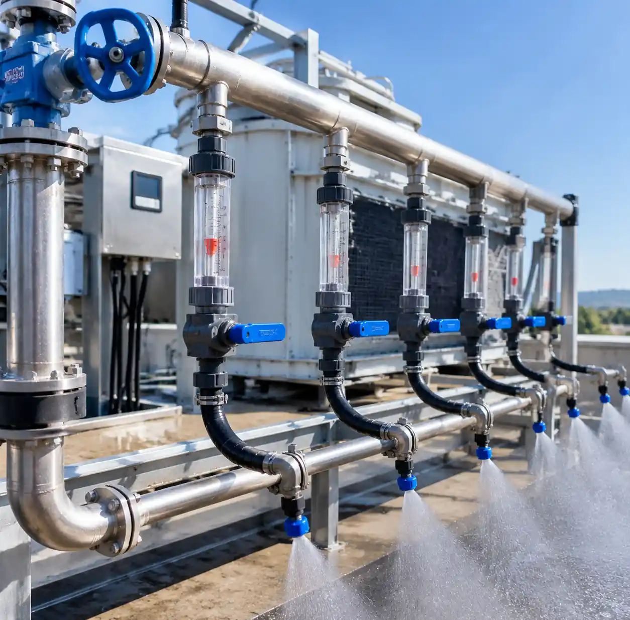 Flow control valves and piping for spray nozzle cooling system
Energy Savings Calculation Framework
Calculating ROI for spray cooling retrofits requires comparing total energy consumption: pumps, fans, and (if applicable) chiller compressors. Spray systems eliminate or drastically reduce compressor runtime, but they do require circulation pumps and, in some cases, compressed air for two-fluid atomization.
Start with baseline energy consumption. If your facility runs a 300 kW chiller with COP of 3.5 for 4,000 hours/year, annual compressor energy is (300/3.5) × 4,000 = 342,857 kWh. Add condenser fan and pump energy—typically another 15-20%—for total baseline consumption around 400,000 kWh.
A properly designed evaporative spray system handling the same 300 kW load would require approximately 18 kW in circulation pumps and 22 kW in induced-draft fans, running continuously when cooling is needed. Annual energy: (18 + 22) × 4,000 = 160,000 kWh. That's a 60% reduction, worth $24,000/year at $0.10/kWh.
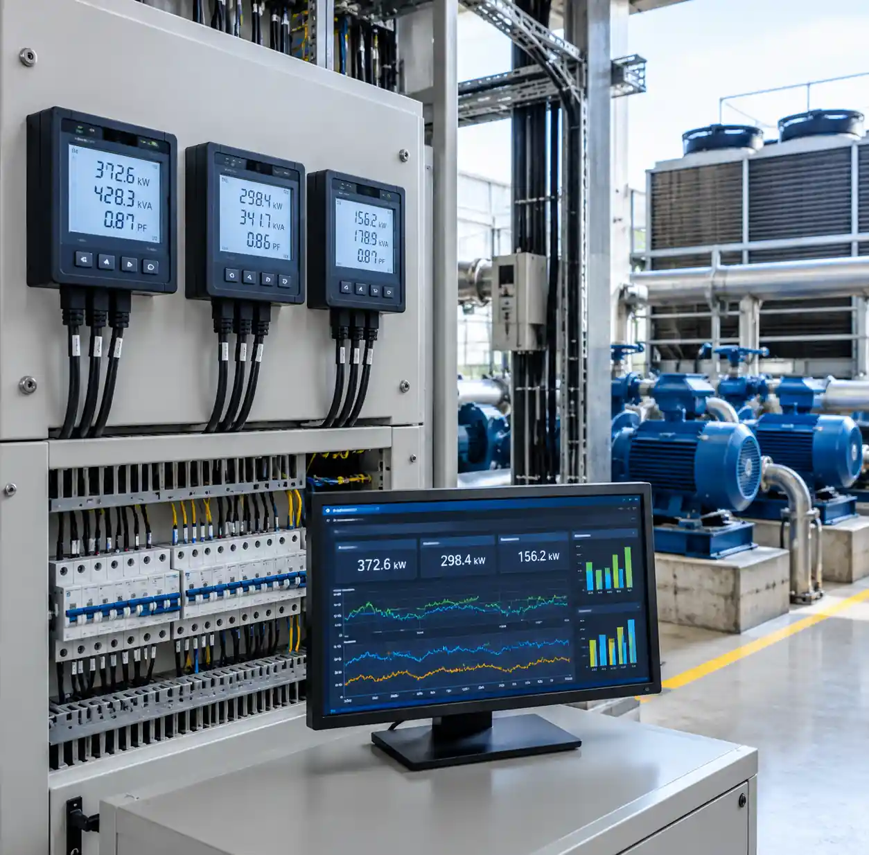 Energy monitoring equipment for spray cooling system performance tracking
But you need to factor in water costs and treatment chemicals. Makeup water at $2/m³ adds $9,600-$14,400 annually (4,800-7,200 m³). Chemical treatment (biocides, scale inhibitors) runs $3,000-$5,000/year depending on cycles of concentration. Net savings: approximately $16,000-$19,000/year with a typical payback period of 14-18 months for a full retrofit.
The ASHRAE Cooling Tower Guide provides detailed psychrometric calculations for different climate zones. Dry climates (relative humidity <40%) see the biggest gains—approach temperatures can hit 1-2°C above wet bulb. Humid climates (RH >70%) still benefit, but approach temperatures widen to 4-5°C, reducing overall system efficiency.
 Before and after comparison of cooling system retrofit with spray nozzles
FAQ
Q: How often do spray nozzles need cleaning or replacement?
A: With proper filtration (25-50 micron screens upstream), stainless nozzles in clean water systems run 18-24 months between maintenance. High-TDS water (>400 ppm) may require quarterly inspection for calcium scale buildup. We've seen nozzles last 5+ years in closed-loop systems with softened makeup water.
Q: Can I retrofit spray nozzles into an existing splash-fill cooling tower?
A: Yes, but you'll need to verify structural capacity for spray headers and ensure adequate clearance above the fill. Most crossflow towers adapt easily. Counterflow towers may require fill replacement to optimize airflow patterns around the spray zone.
Q: What's the minimum water pressure required for effective atomization?
A: Full cone and hollow cone nozzles produce acceptable droplet sizes at 4-6 bar. Below 3 bar, droplets coarsen and evaporation efficiency drops significantly. Fine misting nozzles need 10-15 bar for proper atomization.
Q: How do I prevent legionella growth in spray cooling systems?
A: Maintain water temperature below 20°C in the sump, dose with EPA-registered biocides (typically 2-5 ppm free halogen), and drain stagnant sections during shutdowns. Regular microbiological testing (monthly during cooling season) is essential.
Q: What happens if ambient temperature exceeds design conditions?
A: Approach temperature widens and cooling capacity drops. Systems designed for 35°C dry bulb / 24°C wet bulb may see 15-20% capacity loss at 40°C dry bulb. Oversizing by 10-15% provides operational margin for extreme weather.
Conclusion
Industrial spray cooling systems deliver measurable energy savings when nozzle characteristics match thermal load and environmental conditions. Droplet size, nozzle spacing, and water flow balance determine whether you achieve 30% or 60% energy reductions versus mechanical cooling.
The biggest gains come from rightsizing nozzle capacity rather than over-spraying. Systems running at 70-85% of maximum design flow maintain optimal droplet trajectories and evaporation efficiency, and with variable-frequency drives on circulation pumps, adapt to part-load conditions without sacrificing performance.
Evaporative spray technology reflects broader industry trends: lower energy intensity, reduced refrigerant use, and improved water management. Payback periods under 24 months make spray systems one of the fastest ROI improvements in industrial thermal management.