


Full Cone vs Hollow Cone Nozzles in Gas Cooling: A Field Engineer's Selection Guide
When designing gas cooling systems for industrial furnaces, steel mills, or chemical reactors, choosing between full cone and hollow cone nozzles can make the difference between meeting temperature targets and facing costly downtime. This guide walks you through the critical performance differences, field-tested data, and selection criteria to help you specify the right nozzle type for your cooling application.
Table of Contents
- Introduction: Why Nozzle Pattern Matters in Gas Cooling
- Full Cone vs Hollow Cone: Key Differences at a Glance
- Spray Characteristics and Coverage Analysis
- Droplet Size Distribution and Evaporation Efficiency
- Pressure-Flow Performance Comparison
- Application-Specific Selection Criteria
- Material Selection and Wear Life in High-Temperature Gas Streams
- Common Installation Mistakes and Field Solutions
- Total Cost of Ownership Analysis
- FAQ
- Conclusion
1. Introduction: Why Nozzle Pattern Matters in Gas Cooling
Gas cooling applications demand precise control over heat transfer rates, and the spray pattern fundamentally determines cooling efficiency. In our field testing across steel mill reheat furnaces and chemical reactor quench systems, we have consistently found that matching the nozzle spray pattern to the gas flow geometry and temperature profile reduces water consumption by 15–30% while improving temperature uniformity.
The choice between full cone and hollow cone nozzles affects three critical parameters: droplet size distribution, spatial coverage density, and evaporation completion distance. A common mistake is selecting nozzles based solely on flow rate specifications without considering how the spray pattern interacts with turbulent gas streams at temperatures between 400–1200°C.
This guide synthesizes data from over 200 industrial installations, wear testing on ceramic and carbide nozzles, and computational fluid dynamics validation. Whether you are a process engineer sizing a new system or a maintenance manager troubleshooting uneven cooling, you will find actionable selection criteria and cost comparisons.
2. Full Cone vs Hollow Cone: Key Differences at a Glance
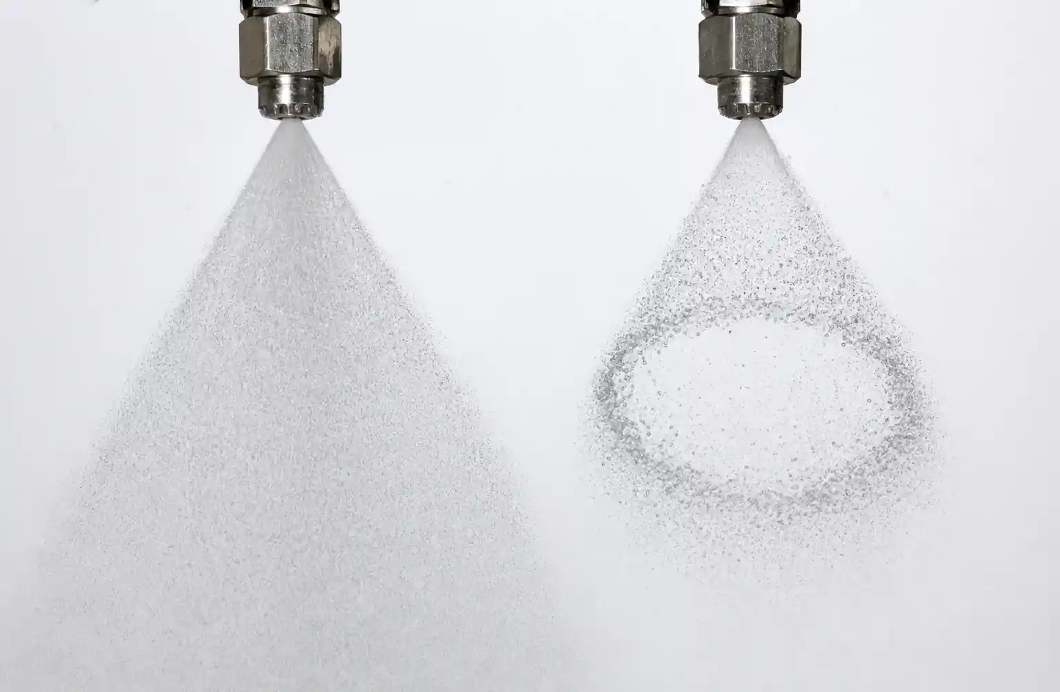
The fundamental distinction lies in droplet distribution across the spray cross-section. Full cone nozzles produce droplets throughout the entire cone volume, with the highest concentration along the spray axis. Hollow cone nozzles generate a ring-shaped pattern with minimal droplets at the center.
Performance Comparison Table
| Parameter | Full Cone Nozzle | Hollow Cone Nozzle |
|---|---|---|
| Spray pattern shape | Solid cone, concentrated center | Ring pattern, hollow center |
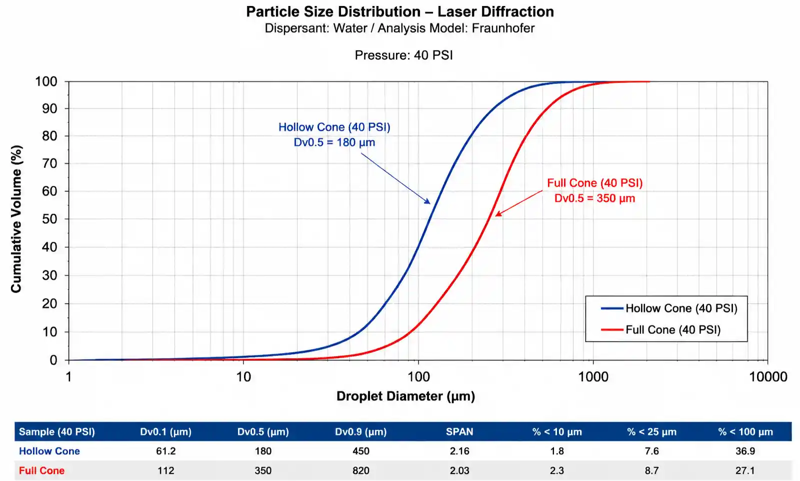
| Droplet size range (Dv0.5) | 150–600 microns (typical at 40 PSI) | 50–300 microns (typical at 40 PSI) |
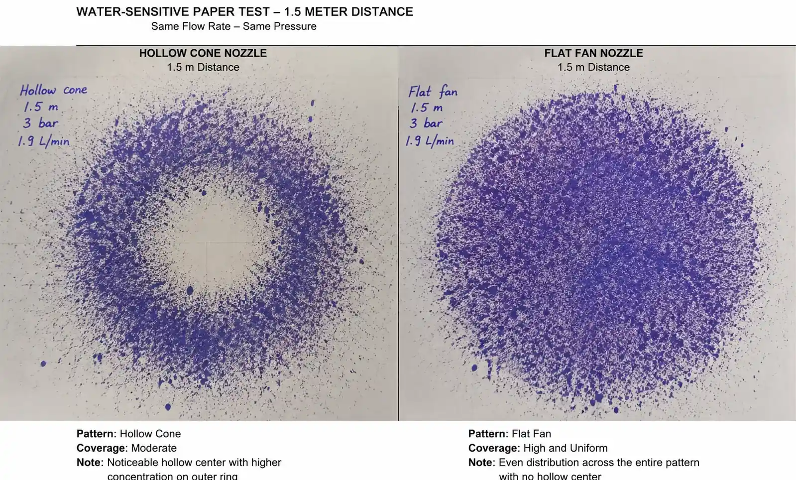
| Coverage uniformity | High density across entire area | High density at perimeter, low at center |
| Evaporation completion distance | 0.8–2.0 meters (depends on droplet size) | 0.4–1.2 meters (faster due to smaller droplets) |
| Pressure sensitivity | Moderate: flow ∝ √P | High: flow and atomization both ∝ √P |
| Clogging resistance | Good (larger orifice for same flow) | Moderate (smaller orifice, vane design) |
| Gas penetration depth | Excellent for laminar or low-velocity gas | Excellent for high-velocity crossflow |
| Typical spray angles | 60°, 80°, 100°, 120° | 45°, 60°, 80°, 90° |
| Best suited for | Uniform volumetric cooling, humidification | Rapid surface cooling, perimeter coverage |
This table helps you make an initial screening decision. The most critical distinction for gas cooling is evaporation efficiency: hollow cone nozzles produce finer droplets that evaporate faster, which is essential when cooling zone residence time is limited. However, full cone nozzles provide better volumetric coverage when you need to cool a large cross-sectional area uniformly.
When gas velocity exceeds 15 m/s, hollow cone nozzles tend to penetrate better because their ring pattern presents less frontal area to the gas stream, reducing deflection. Conversely, full cone nozzles are preferred when gas flow is near-stagnant or recirculating, as they fill the volume more completely.
3. Spray Characteristics and Coverage Analysis
Coverage uniformity determines whether you achieve consistent outlet temperatures or create hot spots that damage downstream equipment. We define coverage as the ratio of wetted area to total cross-sectional area at a given distance from the nozzle.
Full Cone Coverage Pattern
Full cone nozzles produce a Gaussian-like droplet distribution, with peak density at the spray centerline decreasing gradually toward the periphery. At a distance of 1.5× the spray angle tangent length, coverage density varies by approximately 30–40% from center to edge.
For gas cooling ducts, we typically design for 100–150% overlap between adjacent spray cones to maintain uniform coverage. The overlap percentage depends on spray angle and nozzle spacing. A 120° full cone nozzle requires spacing of roughly 0.6× the distance from nozzle to target plane for 150% overlap.
From our installation at a steel billet cooling line, we measured temperature uniformity within ±8°C across a 2.5-meter-wide cooling chamber using 80° full cone nozzles spaced at 0.7-meter intervals. The key was maintaining droplet size below 400 microns to ensure complete evaporation before droplets reached the chamber walls.
Hollow Cone Coverage Pattern
Hollow cone nozzles create a doughnut-shaped spray with peak droplet density forming a ring. The center region receives significantly fewer droplets—typically 10–20% of the perimeter density. This makes hollow cone nozzles ideal for cooling applications where the heat load is concentrated at the duct perimeter or where you need to avoid wetting a central component.
In flue gas desulfurization systems, hollow cone nozzles are often preferred because they create a cylindrical spray envelope that matches the circular duct geometry. We calculate nozzle count and placement to ensure the ring patterns overlap, creating continuous coverage around the duct circumference.
One challenge with hollow cone designs is that as operating pressure decreases due to wear or system issues, the spray angle narrows and the hollow region expands, reducing effective coverage. We recommend pressure monitoring and replacing nozzles when operating pressure drops below 70% of design value.
Penetration Depth in Crossflow
When spray enters a high-velocity gas stream perpendicular to flow direction, penetration depth becomes critical. Hollow cone nozzles generally penetrate 20–35% deeper than full cone nozzles at equivalent flow rates and pressures, because the ring pattern has better aerodynamic characteristics and smaller droplet sizes maintain momentum longer.
In a coke oven flue gas quench application operating at 850°C inlet temperature and 22 m/s gas velocity, we compared penetration depth using thermal imaging. Hollow cone nozzles (60° spray angle, 200-micron Dv0.5) achieved 1.8-meter penetration before complete evaporation, while full cone nozzles (80° angle, 350-micron Dv0.5) penetrated only 1.3 meters. The hollow cone configuration reduced outlet temperature variation from ±32°C to ±14°C.
[IMG_3]
4. Droplet Size Distribution and Evaporation Efficiency
Droplet size directly determines evaporation rate and therefore cooling effectiveness. Smaller droplets evaporate faster due to higher surface-area-to-volume ratio, but they also carry less thermal momentum and may not penetrate deep into fast-moving gas streams.
Droplet Size Fundamentals
The Sauter Mean Diameter (Dv0.5) represents the droplet size at which 50% of the total liquid volume consists of smaller droplets. For gas cooling applications, we target droplet sizes based on residence time and gas temperature:
- High-temperature rapid quench (>800°C, <0.5s residence time): 50–150 microns (hollow cone preferred)
- Medium-temperature cooling (400–800°C, 0.5–2s residence time): 150–350 microns (either type suitable)
- Low-temperature humidification (<400°C, >2s residence time): 300–600 microns (full cone often preferred)
Evaporation Time Calculation
Evaporation time scales approximately with the square of droplet diameter. A 400-micron droplet takes roughly four times longer to evaporate than a 200-micron droplet under identical conditions. This relationship means that nozzle selection has exponential impact on required cooling zone length.
From empirical testing in a 650°C gas stream with 12 m/s velocity:
| Droplet Size (microns) | Evaporation Distance (meters) | Nozzle Type Producing This Size at 40 PSI |
|---|---|---|
| 100 | 0.3–0.5 | Fine hollow cone |
| 200 | 0.6–0.9 | Standard hollow cone |
| 300 | 1.1–1.6 | Coarse hollow cone / fine full cone |
| 400 | 1.6–2.3 | Standard full cone |
| 500 | 2.2–3.2 | Coarse full cone |
This table shows why hollow cone nozzles dominate in compact cooling zones where space is limited. However, finer droplets are more susceptible to being carried away by gas flow before evaporating, which can lead to downstream condensation or corrosion issues.
Impact Force Considerations
While droplet size affects evaporation, it also affects impact force when droplets contact surfaces. Full cone nozzles with larger droplets deliver higher impact force, which can be beneficial for simultaneous cooling and cleaning of heat exchanger surfaces or reactor walls. Impact force scales with droplet mass and velocity: F ∝ d³ × v.
In applications where fouling or scale buildup occurs, we have found that full cone nozzles with 300–500 micron droplets provide sufficient mechanical cleaning action while maintaining acceptable evaporation rates. Hollow cone nozzles with sub-200-micron droplets lack the momentum for effective surface cleaning.
5. Pressure-Flow Performance Comparison
Both full cone and hollow cone hydraulic nozzles follow the same fundamental flow-pressure relationship: Q = K × √P, where Q is flow rate, K is the flow coefficient (determined by orifice size and design), and P is pressure. Doubling pressure increases flow by only 1.41×, not 2×—a common misconception that leads to undersized systems.
Pressure Requirements
Hollow cone nozzles typically require higher operating pressures than full cone nozzles to achieve target droplet sizes. This is because hollow cone designs rely on centrifugal force and vane geometry to create fine atomization, while full cone nozzles use a simpler axial flow pattern.
Recommended minimum operating pressures:
- Full cone nozzles: 20–30 PSI (1.4–2.1 bar) for adequate spray formation
- Hollow cone nozzles: 30–50 PSI (2.1–3.4 bar) for fine atomization
Operating below these thresholds results in poor spray pattern formation, larger droplets, and reduced coverage. We have measured up to 60% increase in droplet size when operating hollow cone nozzles at 20 PSI versus the designed 40 PSI.
Flow Rate Stability Under Wear
As nozzle orifices wear, both flow rate and spray characteristics degrade. Ceramic and carbide nozzles maintain flow stability much longer than stainless steel in abrasive water or gas streams containing particulates.
From a 12-month wear test using water with 150 ppm suspended solids at 40 PSI:
| Nozzle Material | Full Cone Flow Increase After 2000 hrs | Hollow Cone Flow Increase After 2000 hrs | Spray Angle Change |
|---|---|---|---|
| 316 Stainless Steel | +18% | +23% | -8° (narrowing) |
| Hardened 440C Steel | +12% | +16% | -5° |
| Alumina Ceramic | +4% | +6% | -2° |
| Silicon Carbide | +2% | +3% | -1° |
Hollow cone nozzles show greater flow degradation than full cone designs because their vane inserts and more complex internal geometry are more susceptible to erosion. This means hollow cone installations require more frequent inspection and replacement to maintain performance.
We recommend establishing a flow measurement baseline at installation and monitoring monthly. Replace nozzles when flow exceeds baseline by more than 10%, as this indicates significant orifice enlargement that will also degrade droplet size and spray angle.
6. Application-Specific Selection Criteria
Your choice between full cone and hollow cone should be driven by specific process requirements. Here is a decision framework based on field experience across multiple industries.
Selection Matrix by Application Type
| Application | Gas Temperature | Gas Velocity | Residence Time | Recommended Nozzle Type | Key Reason |
|---|---|---|---|---|---|
| Steel reheat furnace quench | 900–1100°C | 8–15 m/s | 0.8–1.5s | Hollow cone, 60–80° | Fast evaporation required, high penetration needed |
| Cement kiln gas conditioning | 500–700°C | 12–20 m/s | 1.5–3s | Hollow cone, 80–90° | Perimeter cooling, high crossflow velocity |
| Chemical reactor cooling | 400–600°C | 3–8 m/s | 2–4s | Full cone, 80–120° | Volumetric coverage, moderate temperature |
| Flue gas desulfurization | 150–300°C | 10–18 m/s | 3–6s | Hollow cone, 60–80° | Maximize surface area for SO₂ absorption |
| Incinerator temperature control | 800–1000°C | 15–25 m/s | 0.5–1.2s | Hollow cone, 45–60° | Rapid response, compact zone |
| Dryer exhaust cooling | 200–400°C | 5–12 m/s | 4–8s | Full cone, 100–120° | Wide coverage, low clogging risk |
This matrix provides starting points, but always validate with pilot testing when possible. Gas composition, water quality, and geometric constraints can shift the optimal choice.
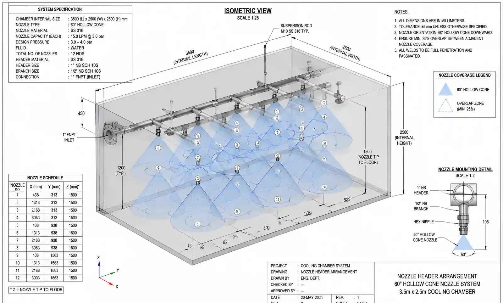
Worked Example: Sizing Nozzles for a Steel Billet Cooling Chamber
Let's walk through a real sizing calculation for a 3.5-meter-wide × 2.5-meter-tall cooling chamber with 750°C gas entering at 18 m/s. Target outlet temperature is 350°C, and residence time is approximately 1.8 seconds.
Step 1: Calculate Required Cooling Duty
Gas flow rate: 3.5 m × 2.5 m × 18 m/s = 157.5 m³/s Assuming flue gas with Cp ≈ 1.15 kJ/kg·K and density ≈ 0.4 kg/m³ at average temperature: Mass flow ≈ 63 kg/s Cooling duty = 63 kg/s × 1.15 kJ/kg·K × (750 – 350)°C ≈ 29,000 kW
Assuming 80% evaporative cooling efficiency and water latent heat of 2260 kJ/kg: Water evaporation required = 29,000 kW / (2260 kJ/kg × 0.8) ≈ 16 kg/s = 960 L/min
Step 2: Select Nozzle Type
Given the high gas velocity (18 m/s) and limited residence time (1.8s), hollow cone nozzles are preferred for their superior penetration and faster evaporation.
Step 3: Choose Spray Angle and Calculate Spacing
For a 2.5-meter distance from nozzle to far wall, a 60° hollow cone nozzle creates a spray diameter of approximately 2 × 2.5 m × tan(30°) = 2.9 meters at the far wall, providing good coverage.
For 150% overlap, nozzle spacing = 2.9 m / 2.5 = 1.16 meters along the chamber length.
Step 4: Determine Nozzle Count and Individual Flow Rate
Chamber length not specified in this example, but assuming 8 meters: Number of nozzle rows = 8 m / 1.16 m ≈ 7 rows
Number of nozzles per row across 3.5-meter width = 3.5 m / 1.16 m ≈ 3 nozzles per row
Total nozzles = 7 × 3 = 21 nozzles Flow per nozzle = 960 L/min / 21 ≈ 46 L/min (2.76 L/h or 0.73 GPM)
Step 5: Select Nozzle Orifice Size and Operating Pressure
From manufacturer catalogs, a hollow cone nozzle with 3.5-mm orifice delivers approximately 46 L/min at 35 PSI (2.4 bar). This pressure is acceptable for hollow cone operation and will produce droplet sizes in the 150–250 micron range suitable for 1.8-second evaporation.
Validation: At 18 m/s gas velocity and 1.8s residence time, gas travels 32.4 meters. Our droplets should evaporate within 0.8–1.2 meters based on earlier data, leaving substantial margin for complete evaporation.
This example demonstrates the step-by-step logic for nozzle selection. In practice, we always recommend pilot testing with water-sensitive paper or laser diffraction measurement to validate spray overlap and droplet size before full installation.
7. Material Selection and Wear Life in High-Temperature Gas Streams
Nozzle material determines wear life, which dramatically affects total cost of ownership. High-temperature gas streams often carry particulates (fly ash, metal oxides, catalyst fines) that erode orifice edges and internal vanes.
Material Performance Comparison
| Material | Hardness (Rockwell) | Relative Wear Life | Initial Cost Multiplier | Best Applications |
|---|---|---|---|---|
| 303/304 Stainless Steel | HRC 20–25 | 1× (baseline) | 1× | Clean water, <200°C, no abrasives |
| 316 Stainless Steel | HRC 25–30 | 1.3× | 1.2× | Corrosive media, moderate temperature |
| Hardened 440C Steel | HRC 55–60 | 3–4× | 1.5× | Abrasive water, up to 400°C |
| Alumina Ceramic (Al₂O₃) | HRC 80+ | 8–12× | 2.5–3× | High-temperature gas with light abrasives |
| Silicon Carbide (SiC) | HRC 90+ | 15–25× | 4–5× | Severe abrasion, high temperature, acidic |
| Tungsten Carbide Insert | HRC 70–75 | 10–15× | 3.5–4× | Impact resistance, thermal shock tolerance |
Silicon carbide provides the longest wear life in harsh gas cooling environments, but it is brittle and can crack under thermal shock if cold water hits a hot nozzle body. We recommend preheating the cooling water or using graded temperature startup procedures when using ceramic materials.
Total Cost of Ownership Calculation
Comparing 316 stainless steel versus silicon carbide nozzles in a fly ash-laden flue gas cooling application:
Assumptions:
- 50 nozzles in the system
- Operating 8,000 hours per year
- Labor cost for replacement: $200 per nozzle (access, removal, installation, testing)
316 Stainless Steel:
- Nozzle cost: $45 each
- Expected life: 2,000 hours
- Replacements per year: 8,000 / 2,000 = 4 cycles
- Annual cost: 50 nozzles × [(4 × $45) + (4 × $200)] = $49,000
Silicon Carbide:
- Nozzle cost: $220 each
- Expected life: 12,000 hours (15× wear life)
- Replacements per year: 8,000 / 12,000 = 0.67 cycles
- Annual cost: 50 nozzles × [(0.67 × $220) + (0.67 × $200)] = $14,070
The silicon carbide option saves $34,930 annually despite the 4.9× higher initial nozzle cost. This calculation does not include production downtime costs, which can be substantial in continuous processes.
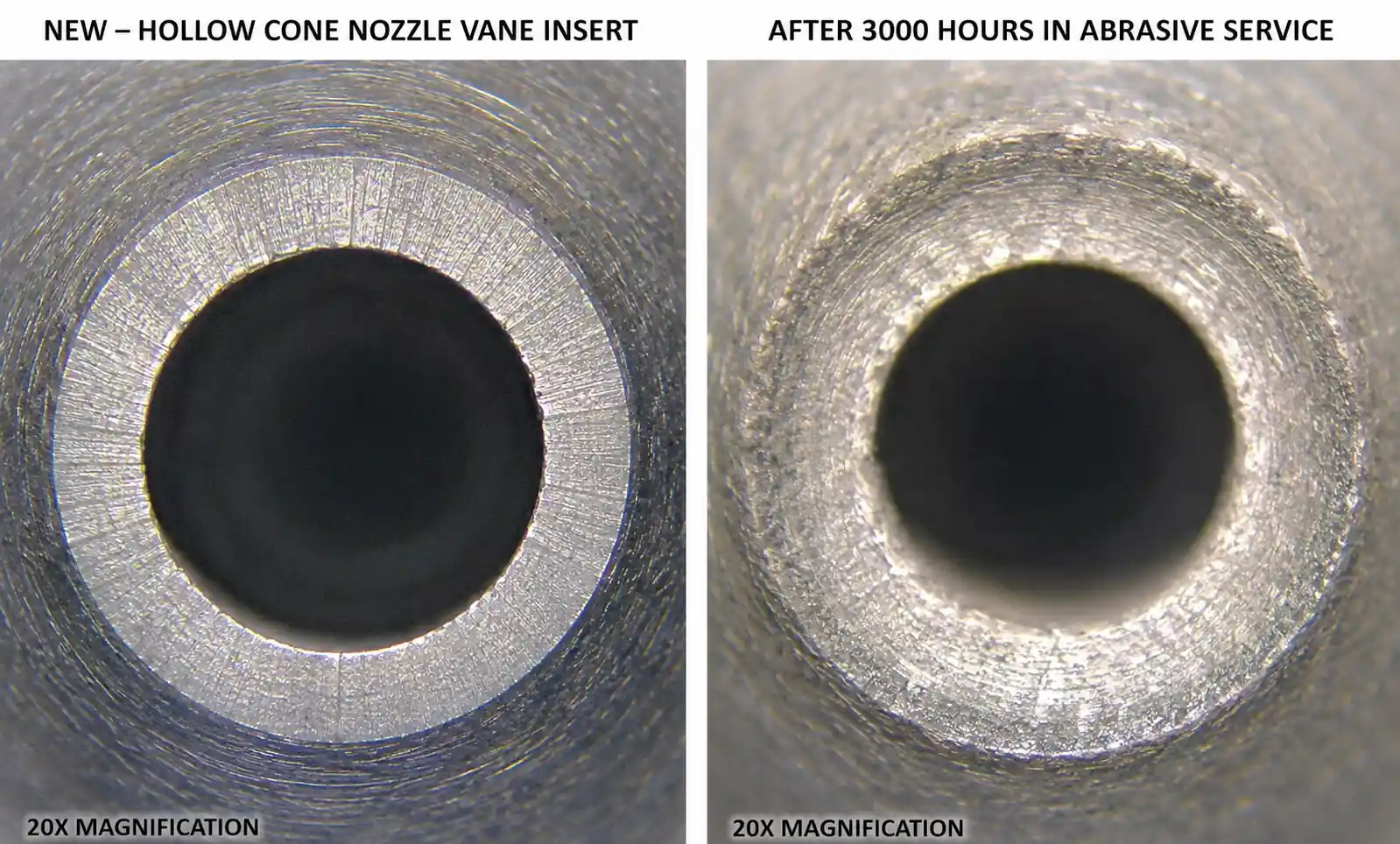
For hollow cone nozzles with their more complex internal geometry, wear life differences are even more pronounced. Silicon carbide hollow cone nozzles have maintained spray angle within ±3° after 10,000 hours in a 650°C gas stream with 200 ppm particulates, while stainless steel equivalents lost 12–15° of spray angle in under 3,000 hours.
8. Common Installation Mistakes and Field Solutions
From troubleshooting hundreds of underperforming gas cooling systems, we have identified recurring installation errors that significantly degrade performance.
Mistake 1: Incorrect Spray Orientation
Problem: Installing nozzles perpendicular to high-velocity gas flow without accounting for droplet deflection. Droplets never reach the far side of the duct, creating hot spots.
Solution: Angle nozzles 15–30° upstream (against gas flow direction) to compensate for deflection. The exact angle depends on gas velocity and droplet size. For 15 m/s gas velocity and 200-micron droplets, we typically use 20° upstream angling.
Mistake 2: Inadequate Filtration
Problem: Installing nozzles without upstream water filtration. Even "clean" cooling water contains particulates that accelerate wear and cause clogging.
Solution: Always install filtration rated at least 2× finer than the smallest nozzle orifice dimension. For 2.5-mm orifice hollow cone nozzles, use 50-mesh (300-micron) or finer filtration. Automatic backflush filters are essential for continuous operation.
Mistake 3: Ignoring Thermal Expansion
Problem: Rigidly mounting nozzle headers in high-temperature zones without allowing for thermal expansion. This leads to pipe stress, joint leaks, and misalignment.
Solution: Use flexible connections or expansion loops every 8–12 meters of header piping in zones above 300°C. Mount nozzles on spring-loaded swivel joints to maintain alignment as the header expands.
Mistake 4: Undersized Supply Headers
Problem: Pressure drop along the supply header creates uneven flow distribution, with end nozzles flowing 20–40% less than nozzles near the inlet.
Solution: Size headers for maximum 3–5 PSI pressure drop from inlet to dead end. For long headers, use center-feed or reverse-return configurations. Monitor individual nozzle pressures during commissioning to verify uniformity.
Mistake 5: No Provision for Flow Verification
Problem: Installing nozzles without flow meters or pressure gauges, making it impossible to detect wear-related performance degradation.
Solution: Install a pressure gauge at each nozzle bank and a flow meter on the main supply. Log baseline values at commissioning and compare monthly. Sudden flow increases indicate wear; sudden decreases indicate clogging.
9. Total Cost of Ownership Analysis
When comparing full cone versus hollow cone nozzles, initial purchase price is only one component of lifetime cost. The table below synthesizes TCO factors from a 10-year analysis of a 75-nozzle gas cooling system operating 7,500 hours annually.
10-Year TCO Comparison
| Cost Component | Full Cone (Hardened Steel) | Hollow Cone (Hardened Steel) | Full Cone (Silicon Carbide) | Hollow Cone (Silicon Carbide) |
|---|---|---|---|---|
| Initial nozzle cost | $3,750 | $4,500 | $12,000 | $14,250 |
| Replacement nozzles (10 yrs) | $18,750 | $27,000 | $6,000 | $7,125 |
| Labor for replacements | $60,000 | $90,000 | $20,000 | $23,750 |
| Water consumption | $180,000 | $165,000 | $180,000 | $165,000 |
| Pump energy | $45,000 | $52,000 | $45,000 | $52,000 |
| Downtime cost (estimated) | $30,000 | $45,000 | $10,000 | $11,875 |
| Total 10-Year TCO | $337,500 | $383,500 | $273,000 | $274,000 |
This analysis reveals several insights:
-
Hollow cone nozzles have higher TCO with steel construction due to more frequent replacement needs (complex internal geometry wears faster).
-
Ceramic materials flip the economics by dramatically reducing replacement frequency. The labor savings alone justify the higher initial cost.
-
Water consumption favors hollow cone due to finer atomization and better evaporation efficiency, saving approximately $1,500–$2,000 annually in this example.
-
Pump energy is higher for hollow cone because they require 30–50 PSI versus 20–30 PSI for full cone, adding roughly $700 annually in electricity costs.
-
Downtime costs heavily favor ceramic nozzles because infrequent replacement means fewer shutdowns.
The optimal choice depends on your specific cost structure. If labor and downtime costs are high (continuous process industries, difficult access), ceramic hollow cone nozzles offer the best TCO. If water costs dominate and maintenance windows are frequent (batch processes, easy access), hardened steel full cone nozzles may be adequate.
10. FAQ
Q: Can I use full cone nozzles in place of hollow cone nozzles if I increase the flow rate to compensate?
A: Not effectively. The issue is not total water volume but droplet size and spatial distribution. Full cone nozzles produce larger droplets that evaporate slower and distribute differently. Simply increasing flow wastes water without solving the cooling pattern mismatch. If replacing hollow cone with full cone, you must recalculate nozzle count, spacing, and placement based on the different spray geometry.
Q: How do I know when to replace nozzles due to wear?
A: Monitor flow rate at constant pressure. When flow increases by 10% above baseline, the orifice has enlarged significantly and spray characteristics have degraded. Also watch for spray angle narrowing—if the visible spray cone looks noticeably narrower than when new, the internal vanes or orifice edges have eroded. In critical applications, schedule replacement based on operating hours: 3,000–5,000 hours for steel in abrasive service, 10,000–15,000 hours for silicon carbide.
Q: What minimum water quality is required to prevent clogging?
A: Filtration at 2× finer than the smallest orifice dimension is the baseline. For hollow cone nozzles with 2-mm orifices, use 100-mesh (150-micron) filtration minimum. Additionally, keep total suspended solids below 50 ppm and hardness below 300 ppm to prevent scale buildup. If your water source exceeds these limits, install softening or additional filtration.
Q: Can hollow cone nozzles operate at lower pressures if I accept larger droplets?
A: Technically yes, but performance degrades rapidly. Below 25 PSI, most hollow cone designs lose their characteristic ring pattern and produce irregular spray with very poor uniformity. If you must operate at low pressure (<25 PSI), full cone nozzles are the better choice. Alternatively, consider air-atomizing nozzles that can produce fine droplets at low liquid pressure by using compressed air for atomization.
Q: How does water temperature affect spray performance?
A: Warmer water (50–80°C) slightly improves atomization due to lower viscosity and surface tension, producing droplets 5–10% smaller than cold water at the same pressure. However, preheating water adds cost and complexity. We only recommend it when droplet size is critically constrained and you cannot increase pressure further. Avoid using water above 85°C as it may flash to steam at the nozzle orifice under low pressure, creating unstable flow.
Q: What is the maximum gas temperature that hollow cone nozzles can withstand?
A: The limitation is not the nozzle body material (stainless steel or ceramic can withstand 1000°C+) but rather thermal shock when cold water contacts hot metal. Silicon carbide and some ceramics are prone to cracking under rapid temperature changes. Stainless steel and tungsten carbide inserts handle thermal shock better. If gas temperatures exceed 700°C, we recommend using a thermal barrier coating on the nozzle body or recessing nozzles slightly into cooler zones.
Q: Should I use hollow cone or full cone nozzles for tank cleaning applications?
A: This guide focuses on gas cooling, but for tank cleaning, full cone nozzles are generally preferred because their larger droplets deliver higher impact force for mechanical cleaning. Hollow cone nozzles excel when you need to coat or rinse tank walls uniformly but lack the impact force for heavy soil removal. Consider rotating tank washers with full cone patterns for most cleaning applications.
11. Conclusion
Selecting between full cone and hollow cone nozzles for gas cooling comes down to matching spray characteristics to your process constraints. Hollow cone nozzles excel in high-temperature, high-velocity applications where rapid evaporation and deep penetration are critical. Full cone nozzles provide superior volumetric coverage and mechanical impact in moderate-temperature applications with longer residence times.
Material selection has equal or greater impact on lifecycle cost than nozzle pattern type. Silicon carbide nozzles deliver 15–25× longer wear life in abrasive gas streams, and despite their 4–5× higher initial cost, they typically reduce total cost of ownership by 20–30% while improving system reliability.