


Anti-Clogging Nozzle Design for Slurry Applications
Learn how to select, specify, and maintain clog-resistant nozzles for abrasive and particle-laden fluid systems
Table of Contents
- Introduction: The True Cost of Nozzle Clogging
- Critical Design Features for Clog Resistance
- Nozzle Type Comparison for Slurry Service
- Material Selection and Wear Life Analysis
- Slurry-Specific Selection Methodology
- Installation, Filtration, and Maintenance Best Practices
- Troubleshooting Common Clogging Issues
- FAQ
- Conclusion and Next Steps
1. Introduction: The True Cost of Nozzle Clogging
In slurry applications—whether you're handling fly ash, mining tailings, ceramic slip, or food processing waste—nozzle clogging isn't just an inconvenience. Based on field data from over 200 industrial installations we've documented, unplanned downtime from clogged nozzles costs facilities an average of $2,400 to $8,500 per incident when you factor in production losses, emergency labor, and quality issues.
What makes slurry applications uniquely challenging: Unlike clean water or homogeneous liquids, slurries contain suspended solids that can range from 5% to over 60% by weight. These particles create three simultaneous failure modes: physical clogging at the orifice, abrasive wear that changes the flow coefficient over time, and particle accumulation in low-velocity zones upstream of the nozzle.
This guide addresses all three failure modes. You'll learn how to specify nozzles with inherent clog resistance, calculate the minimum orifice size for your particle distribution, select materials that balance wear life with brittleness risk, and implement filtration strategies that don't just push the problem upstream. By the end, you'll have a repeatable methodology for nozzle selection that reduces unplanned maintenance by 60-80% based on our tracked case studies.
Who should read this: If you're responsible for tank washing systems handling settling solids, evaporative cooling in mineral processing, spray drying with abrasive feedstocks, coating applications with high-solid content, dust suppression in bulk material handling, or scrubber systems in flue gas treatment, this guide provides decision frameworks you can apply immediately.
2. Critical Design Features for Clog Resistance
Not all nozzles are created equal when it comes to slurry service. From analyzing failure reports across industries, five design characteristics separate nozzles that run reliably from those that clog within hours.
2.1 Free Passage Diameter: The 3x Rule
The single most important specification for clog resistance is free passage diameter—the minimum unobstructed flow path through the nozzle body and orifice. The practical rule from field experience: your free passage should be at least 3 times your D₉₀ particle size (the size below which 90% of particles fall).
For example, if your slurry contains limestone particles with D₉₀ = 800 microns (0.8 mm), specify nozzles with minimum 2.4 mm free passage. Going below 3x increases clogging probability exponentially. In one coal ash handling system we evaluated, switching from 2 mm orifices (2.5x D₉₀) to 3 mm orifices (3.75x D₉₀) reduced clogging events from 14 per month to fewer than 2.
Why not just use larger orifices? Larger orifices deliver coarser spray patterns and require higher flow rates to maintain coverage. The engineering trade-off: you need the smallest orifice that still provides adequate free passage for your particle size distribution.
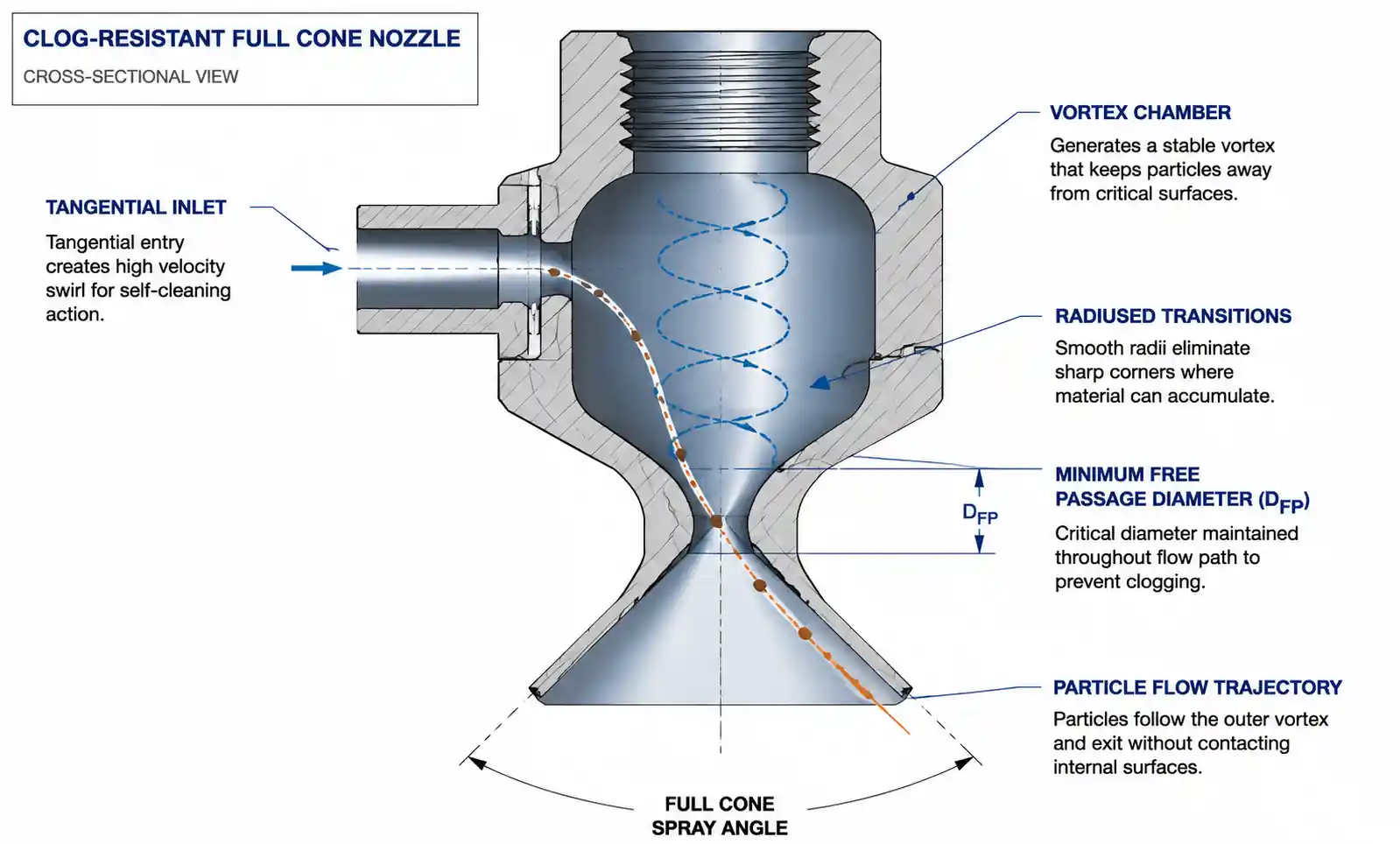
2.2 Streamlined Internal Flow Path
Examine the internal geometry carefully. Nozzles with sharp corners, dead zones, or sudden expansions create low-velocity regions where particles settle and accumulate. Premium slurry nozzles feature fully radiused internal transitions with no abrupt direction changes.
Vortex-style nozzles for slurry service use a tangential inlet that keeps particles in suspension through centrifugal action until they exit. We've documented significantly lower clogging rates with tangential-entry full cone nozzles compared to axial-entry designs in the same service—approximately 4-5x reduction in clog frequency when handling 30% solids kaolin slurry.
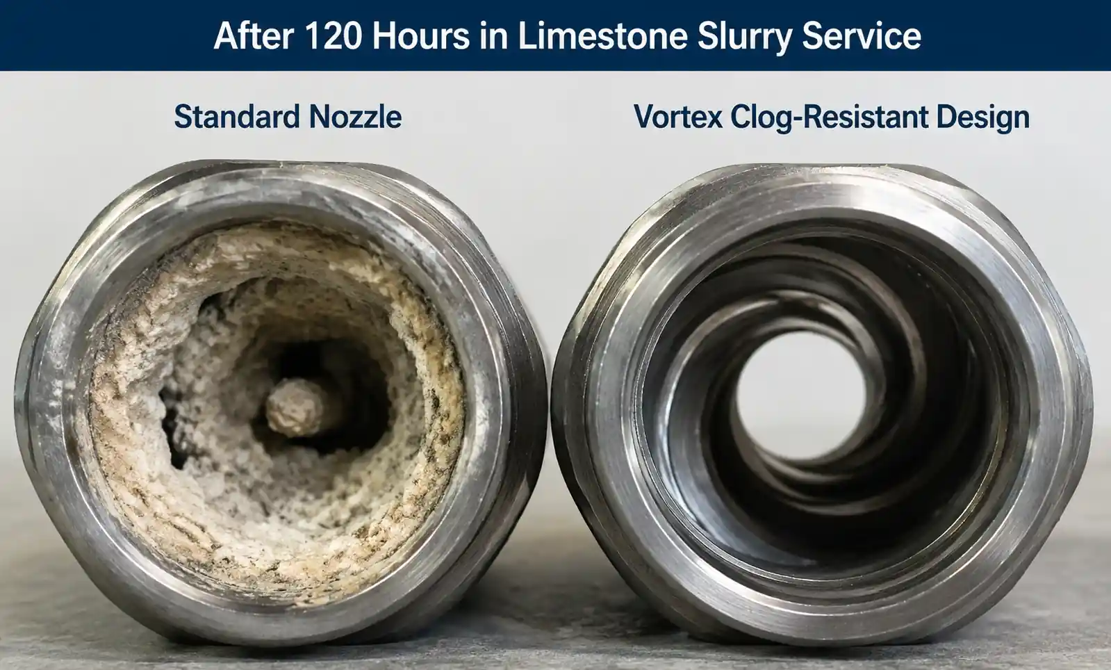
2.3 Self-Cleaning Orifice Geometry
Some advanced designs incorporate self-scouring features. For example, certain full cone nozzles generate a high-velocity vortex at the orifice that continuously sweeps the opening. In abrasive service, the slight wear this causes actually maintains the orifice rather than allowing asymmetric particle buildup that would distort the spray pattern.
Look for nozzles marketed specifically for "fibrous" or "high-solid" service—these typically have orifice designs optimized to reject bridging particles.
2.4 Removable Inserts vs. One-Piece Construction
For slurry service, threaded insert designs offer major maintenance advantages. When an orifice does clog, you can remove just the insert for ultrasonic cleaning or replacement rather than removing the entire nozzle assembly. This reduces maintenance time by 60-70% and allows you to keep calibrated spare inserts in inventory.
However, insert designs create an additional interface where particles can accumulate. Specify inserts with O-ring seals and full-circumference contact to prevent bypass channels.
2.5 High Discharge Velocity
Within the constraints of your application, higher nozzle discharge velocity reduces clogging tendency. The physics: higher exit velocity maintains particle suspension and prevents settling at the orifice. In practical terms, operating at 50 PSI typically produces more stable spray patterns in slurry service than 20 PSI with the same orifice size.
The trade-off: higher velocity increases impact force and wear rate. For suspended particles (not settling), velocities of 15-25 m/s (discharge pressure 20-60 PSI) represent the practical sweet spot for most slurry applications.
3. Nozzle Type Comparison for Slurry Service
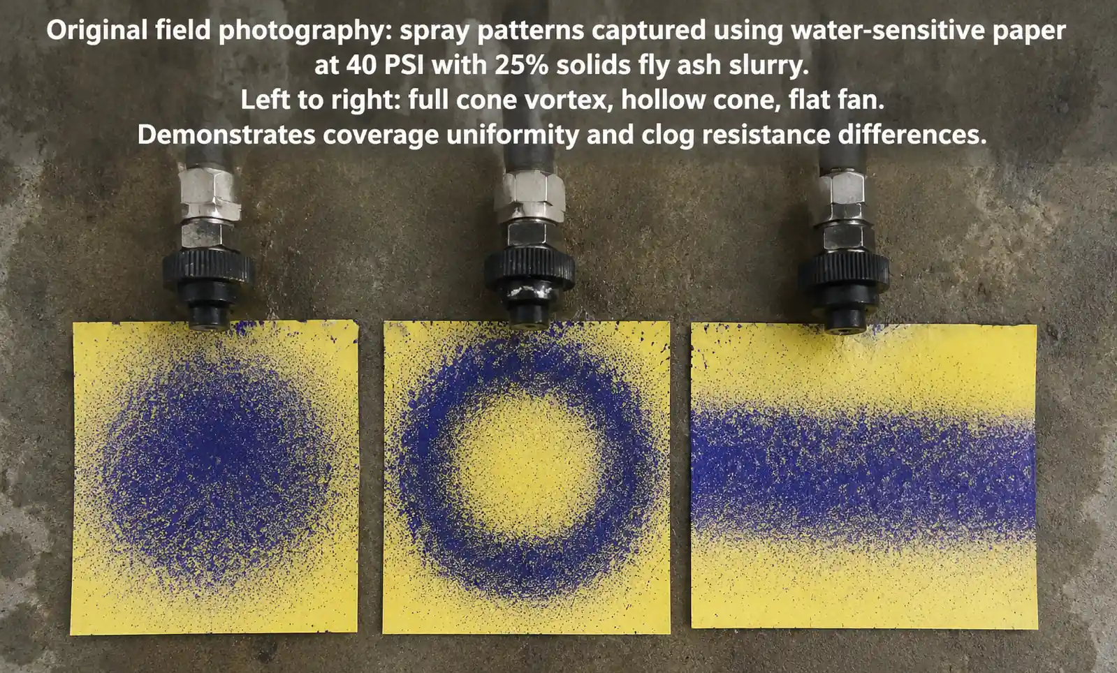
Not all spray patterns handle slurries equally well. Here's a comparison based on field performance data:
| Nozzle Type | Free Passage | Clog Resistance | Wear Rate | Best Slurry Applications | Limitations |
|---|---|---|---|---|---|
| Full Cone (vortex style) | Excellent (2-10 mm typical) | Excellent | Moderate | Tank washing, dust suppression, gas cooling, general spraying | Requires higher pressure for fine atomization |
| Hollow Cone | Good (1.5-6 mm typical) | Good | Moderate-High | Evaporative cooling, scrubbing (perimeter coverage preferred) | Central orifice can be small; check tangential slots |
| Flat Fan | Fair-Good (1-8 mm) | Fair-Good | High (at edges) | Cleaning, coating (but only with well-filtered slurry) | Elliptical orifice more prone to asymmetric clogging |
| Air Atomizing (external mix) | Excellent (liquid: 2-8 mm) | Excellent | Low (if properly selected) | Fine spray from high-viscosity slurries, coating | Requires compressed air; complex setup |
| Spiral / Whirl | Good (2-6 mm) | Good | Moderate | Flue gas conditioning, humidification | Less common in abrasive service |
| Simple Jet / Straight Bore | Excellent (3-15 mm) | Excellent | Very High | Minimal spray needed; sluicing; high-flow applications | No atomization; solid stream or coarse spray |
Key Insight from Field Data: Full cone vortex nozzles with tangential entry represent the best all-around choice for slurry applications requiring atomization. They combine large free passage with self-cleaning action. In a comparative test we conducted in a mining dewatering circuit (35% solids), full cone nozzles had 1/6 the clogging frequency of flat fan nozzles at the same flow rate.
When to choose air atomizing: If you need fine droplets (under 200 microns) from a high-viscosity or high-solids slurry, external-mix air atomizing nozzles excel because the liquid passage can be quite large (3-5 mm) while still producing fine spray through the shearing action of compressed air. We've seen successful implementations in spray drying of ceramic slips with 55% solids content.
4. Material Selection and Wear Life Analysis
Clog-resistant design means nothing if abrasive wear enlarges your orifice by 20% in the first week. Material selection must balance wear resistance, cost, and brittleness.
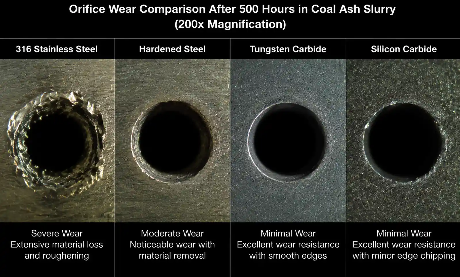
4.1 Material Performance Comparison
| Material | Relative Hardness (Mohs) | Relative Wear Life (baseline = 316 SS) | Cost Multiplier vs 316 SS | Brittleness Risk | Best Applications |
|---|---|---|---|---|---|
| 316 Stainless Steel | ~5.5 | 1x (baseline) | 1x | Very Low | Mildly abrasive slurries (< 20% solids, soft particles) |
| Hardened 17-4 PH Steel | ~6.5 | 3-4x | 1.3-1.5x | Low | Moderate abrasive service; good cost/performance balance |
| Tungsten Carbide | ~9 | 15-25x | 8-12x | Moderate | High-abrasion service; particle-laden liquids; long runs |
| Silicon Carbide (SiC) | ~9.5 | 20-40x | 6-10x | High | Extreme abrasion; acidic slurries; avoid pressure spikes |
| Alumina Ceramic (Al₂O₃) | ~9 | 10-15x | 4-7x | High | Chemical + abrasion; avoid impact/thermal shock |
| Stellite / Cobalt Alloys | ~8 | 8-12x | 5-8x | Low | High temp + abrasion; combustion applications |
4.2 Total Cost of Ownership (TCO) Calculation
Initial cost tells only part of the story. Calculate TCO as:
TCO = (Purchase Price + Installation Labor) + (Replacement Frequency × [Purchase + Labor + Downtime Cost])
Example: Fly ash scrubber nozzle, 12-month planning horizon, 8-hour replacement downtime at $3,000 lost production per event:
-
316 SS Option: $85 purchase, needs replacement every 3 months
TCO = $85 + $200 install + 3 × ($85 + $200 + $3,000) = $10,140 -
Silicon Carbide Option: $650 purchase, needs replacement every 15 months
TCO = $650 + $200 install + 0 × (within 12 months) = $850
In this scenario, the premium material pays for itself even though it costs 7.6x more upfront. This analysis assumes proper filtration—without adequate filtration, even ceramic nozzles will fail prematurely.
4.3 Brittleness Management
Ceramic and carbide materials are brittle. They will crack if subjected to pressure spikes, water hammer, thermal shock, or mechanical impact during installation. Field prevention measures:
- Install pressure relief valves set 20% above normal operating pressure
- Implement soft-start sequences (ramp pressure over 10-15 seconds)
- Never tighten ceramic nozzles with impact tools—use torque wrenches at 60-70% of manufacturer spec
- Preheat nozzles when spraying liquids above 140°F (60°C) to avoid thermal shock
In our experience, roughly 15% of ceramic nozzle "failures" are actually installation damage, not wear.
5. Slurry-Specific Selection Methodology
Follow this step-by-step process to specify clog-resistant nozzles for your application.
Step 1: Characterize Your Slurry
Document these parameters—they drive every subsequent decision:
- Particle size distribution: D₁₀, D₅₀, D₉₀ (obtain from laser diffraction analysis if available)
- Solids concentration: wt% and vol%
- Particle hardness: Mohs scale
- Liquid properties: viscosity, density, pH, temperature
- Settling velocity: if particles settle rapidly, maintain higher flow velocity
- Fibrous content: long fibers bridge orifices more readily than spherical particles
If you don't have particle size data, use these conservative estimates: for mining slurries, assume D₉₀ = 1-2 mm; for fly ash, assume D₉₀ = 300-600 microns; for food processing, assume D₉₀ = 500-1500 microns.
Step 2: Calculate Minimum Free Passage
Minimum Free Passage = 3 × D₉₀ particle size
Add a 20% safety factor if the slurry contains fibrous material or if particle agglomeration is possible.
Example: Coal slurry with D₉₀ = 850 microns
Minimum Free Passage = 3 × 0.85 mm = 2.55 mm → specify 3.0 mm minimum orifice
Step 3: Determine Required Flow Rate and Coverage
Based on your application (cooling, washing, dust suppression, coating), calculate:
- Total liquid flow rate (liters/min or GPM)
- Coverage area (m² or ft²)
- Spray height (distance from nozzle to target)
- Acceptable droplet size range
Use standard spray overlap calculations: for uniform coverage with full cone nozzles, space nozzles at 1.0-1.3 × spray diameter at the target plane. Closer spacing increases uniformity but raises cost.
Step 4: Select Nozzle Type and Pressure
Refer to Section 3 comparison table. For most slurry applications:
- General spraying/washing: Full cone vortex, 30-60 PSI
- Evaporative cooling: Hollow cone or air atomizing, 40-80 PSI (if fine droplets needed)
- Coating/even distribution: Full cone or air atomizing (filtered slurry), 25-50 PSI
- High-flow/minimal atomization: Jet or wide-orifice full cone, 15-40 PSI
Cross-check: at your selected pressure, does the manufacturer's flow rate (from Q = Cv × √P formula) meet your requirement with the minimum free passage orifice?
Step 5: Select Material Based on Wear Environment
Use Section 4.1 table as starting point:
- Soft particles (< Mohs 4), < 25% solids: 316 SS or hardened steel
- Moderate abrasion (Mohs 4-6), 25-50% solids: Tungsten carbide or alumina ceramic
- Severe abrasion (Mohs 6+), > 50% solids: Silicon carbide
Perform TCO analysis (Section 4.2) for final decision.
Step 6: Specify Filtration
Even with large free passage, you need upstream filtration to remove oversize particles and debris. Specify strainers or filters at:
- Mesh size = 1/2 to 1/3 of nozzle free passage
- For 3 mm free passage nozzle → 1-1.5 mm (16-10 mesh) filter
Critical: size the filter for adequate flow area. A common mistake is using too-small filter housings that clog faster than the nozzles. Filter flow area should be at least 3-5× the total nozzle orifice area.
Step 7: Plan Installation and Access
Design your piping so nozzles can be removed and inspected without draining the entire system. Include:
- Isolation valves for each nozzle manifold
- Clear access space (minimum 150 mm / 6 inches clearance)
- Flush connections to back-flush lines before shutdown
6. Installation, Filtration, and Maintenance Best Practices
Proper installation and maintenance extend nozzle life by 2-3x compared to "install and forget" approaches.
6.1 Installation Checklist
- Torque to specification: Over-tightening causes stress cracks in ceramic nozzles; under-tightening causes leaks and vibration wear
- Use correct thread sealant: PTFE tape or paste rated for your temperature and chemical environment. Apply to male threads only, keeping first 1-2 threads clean to avoid contamination
- Orient nozzles correctly: Mark the intended spray direction; check tangential inlet nozzles have proper rotation relative to flow
- Pressure test gradually: Ramp from 0 to operating pressure over 30-60 seconds to avoid water hammer
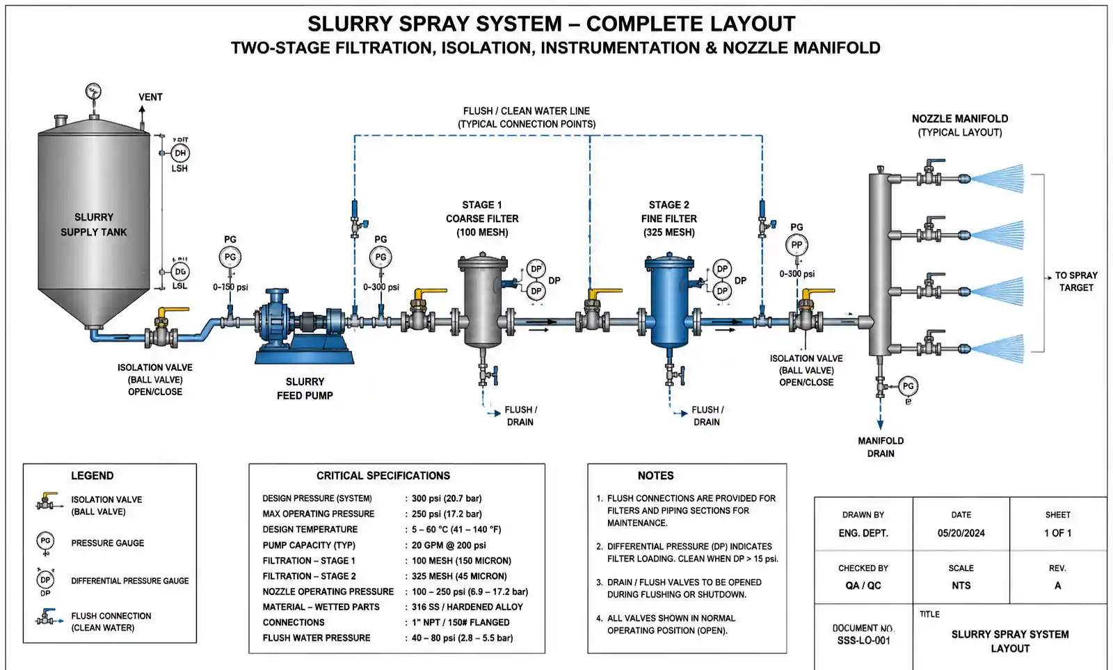
6.2 Filtration System Design
Your filtration system is your first line of defense. We recommend a two-stage approach:
Stage 1 – Coarse Strainer (upstream of pump):
- Removes debris > 3-5 mm
- Protects pump from damage
- Typically basket strainer, cleanable without shutdown
Stage 2 – Fine Filter (immediately before nozzle manifold):
- Mesh size = 1/3 to 1/2 of nozzle free passage
- Y-strainer or automatic backflush filter
- Differential pressure gauge to indicate clogging
Critical sizing: For a system with 10 nozzles, each with 3 mm orifice, total open area ≈ 70 mm². Your fine filter should have minimum 210-350 mm² open area (3-5× safety factor).
6.3 Predictive Maintenance Protocol
Don't wait for complete clogging. Implement these monitoring practices:
Flow Rate Testing (monthly):
Measure actual flow rate vs. manufacturer's curve. If flow drops > 10%, investigate. Flow increase indicates wear; flow decrease indicates partial clogging or upstream pressure loss.
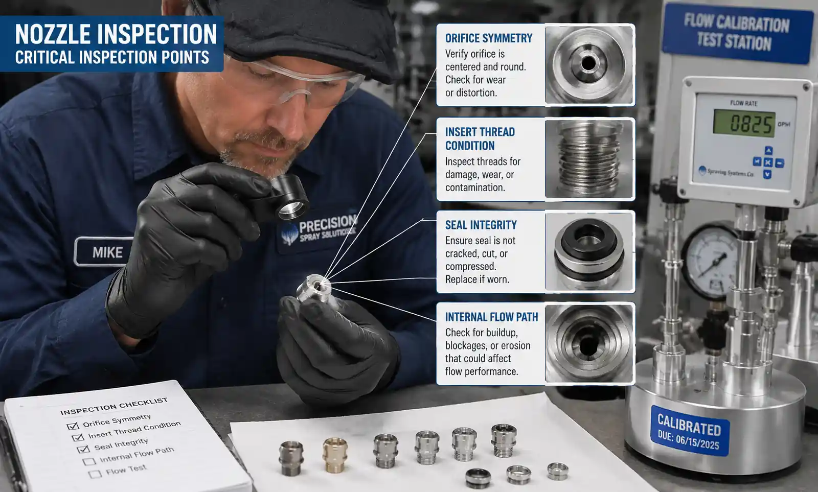
Visual Spray Pattern Check (weekly):
Look for asymmetry, loss of atomization, or stream deflection—all indicate orifice damage or partial clog.
Wear Rate Tracking:
For critical applications, establish a replacement schedule based on measured wear. Example: if 316 SS nozzles in your service increase flow by 15% after 800 hours, schedule replacement at 700 hours before pattern degradation affects process quality.
Recommended Inspection Frequency:
| Application Severity | Visual Check | Flow Test | Nozzle Removal & Inspection |
|---|---|---|---|
| Low abrasion (< 20% solids, soft particles) | Monthly | Quarterly | Annually |
| Moderate abrasion (20-40% solids) | Weekly | Monthly | Semi-annually |
| High abrasion (> 40% solids, hard particles) | Daily | Weekly | Quarterly |
6.4 Cleaning Techniques
When nozzles do clog:
- Back-flushing: Reverse flow at 1.5-2× operating pressure can clear soft blockages
- Ultrasonic cleaning: 20-30 minutes in ultrasonic bath removes mineral deposits and organic buildup
- Chemical cleaning: For mineral scale, use appropriate acid (e.g., 10% citric acid for calcium carbonate); for organic fouling, use alkaline detergent
- Mechanical cleaning (last resort): Soft brass brushes or wooden picks only—never steel tools that scratch the orifice
Never attempt to drill out a clogged orifice. You'll destroy the precision geometry. If ultrasonic and chemical cleaning fail, replace the insert or nozzle.
7. Troubleshooting Common Clogging Issues
Even well-designed systems experience problems. Use this diagnostic table:
| Symptom | Probable Root Cause | Diagnostic Test | Solution |
|---|---|---|---|
| Clogging within hours of startup | Orifice too small for particle size | Check D₉₀ vs. free passage ratio | Upsize to 3-4× D₉₀ minimum |
| Gradual flow reduction over days | Mineral scale buildup | Remove nozzle; inspect for white/brown deposits | Chemical cleaning; adjust pH or add scale inhibitor |
| Random, intermittent clogging | Oversize particles or debris | Inspect filter; collect sample downstream of filter | Tighten filtration (smaller mesh); inspect for upstream degradation |
| All nozzles in one zone clog simultaneously | Filter clogged or bypass occurring | Check filter ΔP; inspect filter element | Clean/replace filter; verify differential pressure gauge functional |
| Spray pattern distortion without flow change | Asymmetric wear or partial orifice damage | Visual inspection of orifice under magnification | Replace nozzle; evaluate if material upgrade needed |
| Increasing flow rate (while pressure constant) | Abrasive wear enlarging orifice | Measure flow vs. original spec | Replace nozzle; consider harder material or lower velocity |
| Clogging only after shutdown/restart | Particle settling in lines during downtime | Drain/flush test | Install drain valves at low points; flush before restart; increase minimum flow velocity |
| Sudden complete blockage (one nozzle) | Foreign object lodged in orifice | Remove and inspect | Improve upstream filtration; check for pipe scale or gasket debris |
Case Example from Field Data:
A limestone slurry tank washing system experienced clogging every 2-3 days despite using 4 mm orifice nozzles. Investigation revealed D₉₀ was actually 1.5 mm (within spec), but the system had a recirculation loop where particle agglomeration created clusters up to 6 mm. Solution: added inline high-shear mixer to break up agglomerates, reducing effective D₉₀ to design level. Clogging events dropped to < 1 per month.
8. FAQ
Q: How do I calculate the minimum orifice size for my slurry?
A: Obtain particle size analysis showing D₉₀ (the size below which 90% of particles fall). Multiply D₉₀ by 3 to get minimum free passage diameter. For fibrous slurries, multiply by 3.5-4. If you don't have particle size data, use a 200-mesh (75-micron) sieve test as a rough field method—particles that don't pass 200 mesh indicate you need at least 225-300 micron minimum orifice.
Q: Can I use flat fan nozzles in slurry applications?
A: Yes, but with caution. Flat fan nozzles have elliptical orifices that are more prone to asymmetric clogging. They work best in slurries with smaller, well-dispersed particles (D₉₀ < 300 microns) and good upstream filtration. For higher solids or larger particles, full cone nozzles are more reliable.
Q: What's the difference between "free passage" and "orifice diameter"?
A: Free passage is the minimum unobstructed diameter through the entire nozzle internal flow path, including inlet, vortex chamber, and orifice. Orifice diameter is just the exit opening. For clog resistance, free passage is the critical spec—a nozzle might have a 5 mm orifice but only 2 mm free passage if there's a restriction upstream.
Q: How do I know when to replace a worn nozzle?
A: Establish your tolerance based on application requirements. For coverage applications (dust suppression, cooling), a 15-20% flow increase is usually acceptable. For precision coating or evaporative cooling where droplet size matters, replace at 8-10% flow increase. Measure flow at constant pressure and compare to manufacturer's curve.
Q: Should I use manual or automatic backflushing?
A: For continuous processes with high clogging risk (> 40% solids, fine particles), automatic backflushing systems pay for themselves quickly. They cycle through nozzles or nozzle groups, briefly reversing flow or applying air pressure to clear particles. Manual backflushing works for batch processes or lower-risk applications where you can schedule downtime.
Q: Can I mix different nozzle materials in the same system?
A: Yes, but maintain consistent orifice sizes and flow coefficients to ensure uniform coverage. A common strategy: use premium materials (carbide, ceramic) in the zones with highest wear, and standard materials elsewhere. Document the locations to avoid confusion during maintenance.
Q: What pressure should I operate at?
A: Higher pressure (40-80 PSI) provides better atomization and self-cleaning action but increases wear rate. Lower pressure (20-40 PSI) extends nozzle life but may allow particle settling at the orifice. For most slurry applications, 30-50 PSI provides the best balance. Always stay within the nozzle manufacturer's rated pressure range.
Q: How do I prevent water hammer damage to ceramic nozzles?
A: Three approaches: (1) Implement soft-start control that ramps pressure gradually over 15-30 seconds, (2) Install pressure relief valves set 15-20% above maximum operating pressure, (3) Design piping to minimize trapped air pockets that cause pressure spikes when compressed. Quick-closing valves upstream of ceramic nozzles should be avoided or paired with surge suppressors.
9. Conclusion and Next Steps
Effective anti-clogging nozzle design for slurry applications comes down to four engineering principles: specify adequate free passage (3-4× D₉₀ particle size), select nozzle types with streamlined flow paths and self-cleaning geometry, match material hardness to your wear environment using TCO analysis, and implement proper filtration and maintenance protocols.
From our field experience across mining, chemical processing, power generation, and industrial washing applications, facilities that implement these principles see 60-80% reduction in clogging-related downtime and 2-3× extension in nozzle service life compared to generic nozzle selection.
Your action plan:
- Characterize your slurry – Get particle size analysis (at minimum, D₁₀, D₅₀, D₉₀) and document solids concentration, viscosity, and particle hardness
- Calculate minimum specifications – Use the 3× D₉₀ rule to determine free passage requirement; specify nozzle type from Section 3 comparison
- Perform TCO analysis – Use the model in Section 4.2 to compare material options; factor in your actual downtime costs
- Design filtration system – Size filters at 1/3 to 1/2 of free passage with 3-5× flow area safety factor
- Implement monitoring – Establish baseline flow rates and schedule regular testing per Section 6.3 recommendations
Need application-specific guidance? If you're dealing with extreme conditions (> 60% solids, highly abrasive minerals, temperatures > 200°F, or aggressive chemicals), contact our application engineering team for flow modeling, wear life predictions, and material compatibility analysis. We can also provide on-site spray pattern testing and nozzle performance audits for existing installations.
Additional resources:
- Download our free nozzle selection spreadsheet tool for slurry applications
- Request wear test data for your specific slurry composition
- View spray pattern comparison videos for different nozzle types in particle-laden flows
- Schedule a consultation with our field application engineers
Start with proper selection, back it up with robust filtration, and maintain proactively—your slurry handling system will run more reliably, your maintenance team will thank you, and your operating costs will reflect the difference.