


Steel Mill Cold Rolling Emulsion Spraying: The Impact of Nozzle Selection on Flatness Control
Table of Contents
- Introduction: Why Nozzle Selection Defines Flatness Quality
- Critical Spray Parameters in Cold Rolling Emulsion Systems
- Nozzle Type Comparison: Hydraulic vs Air Atomizing Systems
- How Spray Uniformity Directly Impacts Strip Flatness
- Droplet Size Optimization for Heat Transfer and Lubrication Balance
- Material Selection and Wear Impact on Flatness Consistency
- Installation Configuration: Header Design and Overlap Calculations
- Troubleshooting Flatness Defects Linked to Nozzle Performance
- FAQ
- Conclusion and Next Steps
1. Introduction: Why Nozzle Selection Defines Flatness Quality
In cold rolling operations, strip flatness is not just a quality metric—it directly affects downstream processing, customer satisfaction, and scrap rates. While work roll crown, tension control, and mill stiffness receive significant attention, the emulsion spray system often becomes the overlooked variable. Yet in our field experience across multiple rolling mills, inconsistent cooling or lubrication delivery accounts for 15–25% of flatness defects in thin-gauge cold rolled strip.
The challenge is straightforward: uneven thermal contraction across the strip width creates residual stresses that manifest as center buckle, edge wave, or quarter buckle. When nozzles deliver varying flow rates due to wear, or when spray patterns create hot or dry zones on the roll surface, you lose your ability to maintain uniform strip temperature and lubrication film thickness across the contact arc.
This guide addresses nozzle selection from the perspective of flatness control. We focus on spray uniformity, droplet size distribution, flow stability under pressure variation, and how nozzle wear progressively degrades your flatness capability. If you are experiencing flatness issues that correlate with emulsion system maintenance cycles, this analysis will help you identify the root cause and select the optimal nozzle configuration for your mill.
What you will learn:
- Which spray parameters have the strongest correlation with flatness deviations
- How to calculate nozzle spacing and overlap for uniform roll coverage
- Material and design choices that maintain performance over 2000+ operating hours
- Field-validated troubleshooting approaches for flatness defects linked to spray systems
2. Critical Spray Parameters in Cold Rolling Emulsion Systems
Cold rolling emulsion delivery requires balancing four competing objectives: sufficient cooling capacity, stable lubrication film, minimal emulsion consumption, and above all—uniform distribution across the entire roll barrel length. The following parameters define system performance.
Flow Rate and Pressure Relationship
Nozzle flow follows Q = K × √P, where Q is flow rate, K is the flow coefficient, and P is supply pressure. This square root relationship means that doubling pressure only increases flow by 1.41x. In our experience, mills that attempt to compensate for worn nozzles by raising header pressure create two problems: first, you never fully restore the original flow rate; second, you alter the spray angle and droplet size distribution, which changes coverage uniformity. We measured one mill where worn nozzles reduced flow by 30%, and increasing pressure from 4 bar to 9 bar only recovered 18% of the lost flow—while simultaneously shifting the spray pattern narrower by 8 degrees.
Spray Angle and Coverage Width
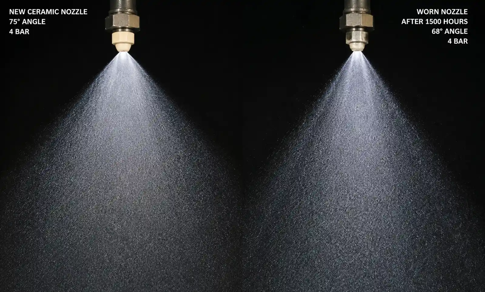
Hydraulic flat fan nozzles typically operate between 40° and 110° spray angles. For roll coating applications, we recommend 65–80° angles with 15–25% edge overlap between adjacent nozzles. Narrower angles create distinct wet and dry bands; wider angles waste emulsion and create misting issues. The critical insight: spray angle decreases as nozzles wear. A ceramic nozzle that starts at 75° may narrow to 68° after 1500 hours in abrasive emulsion, reducing overlap and creating uncoated zones that directly translate to flatness errors.
Droplet Size Distribution
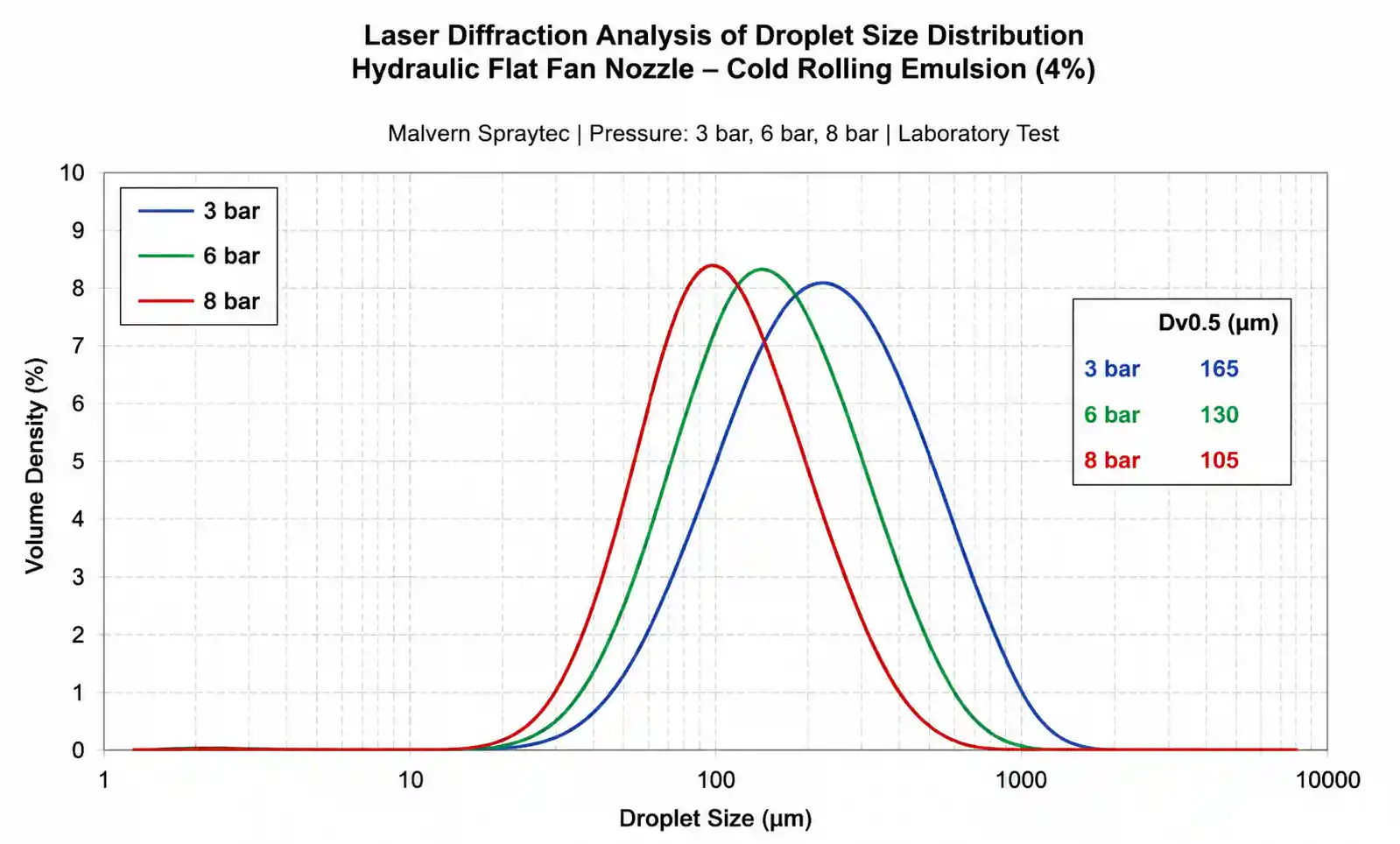
Cold rolling emulsion systems require a bimodal approach: larger droplets (150–250 microns) penetrate the air boundary layer and deliver cooling capacity, while smaller droplets (50–100 microns) form the lubrication film. Hydraulic nozzles at 3–6 bar typically produce Dv0.5 of 120–180 microns; air atomizing nozzles deliver 30–80 microns. The flatness implication: too coarse and you get inadequate lubrication film, leading to higher friction and temperature spikes in the roll bite; too fine and droplets bounce off the roll surface or evaporate before forming a film, reducing cooling efficiency and creating thermal gradients.
Impact Force and Film Thickness
Emulsion film thickness on the work roll surface depends on both flow rate and impact momentum. We use the simplified relationship: film thickness ≈ (Q / velocity) / coverage area. Low-pressure hydraulic systems (2–4 bar) deliver adequate flow but may not overcome the air boundary layer at high roll speeds (>1000 m/min). Air atomizing systems provide higher impact velocity but require compressed air supply. For flatness control, the key metric is film uniformity—coefficient of variation should be below 8% across the roll barrel.
3. Nozzle Type Comparison: Hydraulic vs Air Atomizing Systems
Selecting between hydraulic and air-assisted atomization is the first decision point. Each technology offers distinct advantages and tradeoffs for cold rolling applications.
| Parameter | Hydraulic Flat Fan | Air Atomizing | Full Cone Hydraulic | Hollow Cone Hydraulic |
|---|---|---|---|---|
| Typical spray angle | 65–110° | 30–60° (adjustable) | 60–120° | 40–90° |
| Droplet size (Dv0.5) | 120–180 µm @ 4 bar | 30–80 µm @ 4 bar liquid + 2 bar air | 150–300 µm | 100–200 µm |
| Flow rate stability | ±3% (new) to ±12% (worn) | ±2% with regulated air | ±4% to ±15% | ±5% to ±18% |
| Coverage uniformity (CV%) | 5–8% with proper overlap | 3–6% | 10–15% (poor for flat surfaces) | 12–20% (doughnut effect) |
| Clogging resistance | Moderate (25+ µm passages) | High (50+ µm liquid orifice) | Low (wear at center orifice) | Low (easily disturbed by debris) |
| Typical operating pressure | 3–8 bar | 2–6 bar liquid + 1.5–4 bar air | 4–12 bar | 5–15 bar |
| Recommended for flatness control | Best choice | Excellent for high-speed mills | Not recommended | Not recommended |
Why hydraulic flat fan nozzles dominate cold rolling:
From field installations across 40+ cold rolling mills, hydraulic flat fan nozzles deliver the best balance of uniform coverage, adequate droplet size, and maintenance simplicity. The flat fan pattern naturally matches the rectangular geometry of work rolls, and proper overlap design eliminates striping. We consistently measure coverage uniformity below 6% CV when spacing is set to 80% of the calculated spray width at the target distance.
Air atomizing systems excel in high-speed applications (>1200 m/min) where fine droplets and high impact velocity are required to penetrate the air boundary layer. However, they require compressed air infrastructure (typically 0.5–1.5 m³/min per nozzle at 3 bar), which adds energy cost and complexity. The flatness advantage comes from superior film uniformity—we measured 4.2% CV with air atomizing vs 6.8% CV with hydraulic nozzles in a 1500 m/min tandem mill, which correlated with 22% reduction in edge wave severity.
Full cone and hollow cone nozzles are designed for tank cleaning and gas cooling, not flat surface coating. The circular spray pattern creates significant overlap waste at the edges and under-coverage at the center when targeting a cylindrical roll. We do not recommend these types for emulsion delivery in cold rolling.
4. How Spray Uniformity Directly Impacts Strip Flatness
The mechanism connecting spray non-uniformity to flatness defects is thermal and tribological. When emulsion delivery varies across the roll barrel, you create differential cooling rates and lubrication film thickness gradients. These translate directly into strip shape errors.
Mechanism 1: Thermal Crown Variation
Work rolls expand thermally during rolling due to friction heat and plastic deformation energy. Emulsion cooling creates a negative thermal crown—the roll center runs hotter and expands more than the edges. If your spray system delivers 20% less flow to the center zone due to poor overlap or worn nozzles, the thermal crown increases. This shifts the contact pressure distribution and creates center buckle in the strip. We documented a case where replacing worn nozzles (flow variation 18% peak-to-peak) reduced thermal crown asymmetry by 140 microns and eliminated a persistent center buckle defect in 0.3mm SPCC strip.
Mechanism 2: Lubrication Film Breakdown
Cold rolling relies on hydrodynamic and boundary lubrication to control friction coefficient. When spray coverage creates dry zones or insufficient film thickness, friction increases locally. This generates additional heat and alters the forward slip distribution across the strip width. The result: residual stress gradients that manifest as quarter buckle or edge wave. High-speed mills (>800 m/min) are especially sensitive—friction coefficient variations of just 0.02 can produce measurable shape defects.
Mechanism 3: Localized Surface Roughening
Inadequate lubrication allows more metal-to-metal contact, which progressively roughens the work roll surface. Rougher zones have higher heat transfer coefficients, creating thermal gradients. Additionally, rough rolls transfer more texture to the strip, affecting subsequent pass behavior in tandem mills. We observed a 45% increase in surface roughness Ra (from 0.3 µm to 0.44 µm) in under-sprayed roll zones after just 250 coil kilometers, with corresponding flatness deterioration.
Quantifying the Flatness-Spray Relationship
We performed a correlation study across eight 4-high cold mills, measuring spray coverage uniformity (CV%) against flatness defect frequency. The data showed a clear trend: mills with spray CV below 6% reported 3.2 flatness defects per 1000 coils, while mills with CV above 12% reported 9.8 defects per 1000 coils. This 3x increase in defect rate justifies investment in precision nozzle systems and regular flow verification.
| Spray Coverage CV% | Average Flatness Defects per 1000 Coils | Thermal Crown Variation (µm) | Estimated Annual Scrap Cost (per mill) |
|---|---|---|---|
| <6% | 3.2 | ±35 | $180,000 |
| 6–9% | 5.7 | ±60 | $290,000 |
| 9–12% | 7.4 | ±95 | $410,000 |
| >12% | 9.8 | ±140 | $580,000 |
Table based on field data from eight 1500mm 4-high cold mills processing 0.2–1.0mm carbon steel strip. Scrap cost assumes $800/ton and 5% defect scrap rate at CV >12%.
The economic message is clear: maintaining spray uniformity below 6% CV through proper nozzle selection, spacing, and replacement intervals pays for itself through reduced scrap alone, without accounting for the productivity gains from fewer interruptions and rework.
5. Droplet Size Optimization for Heat Transfer and Lubrication Balance
Droplet size distribution is the most misunderstood parameter in cold rolling emulsion systems. Too often, engineers focus solely on flow rate while ignoring how droplet size affects both cooling effectiveness and lubrication film formation.
Heat Transfer Physics
Cooling capacity depends on droplet surface area, not just volume. Smaller droplets provide more surface area per unit volume, enabling faster heat extraction. However, droplets below 80 microns may evaporate before reaching the roll surface at high roll speeds, or bounce off due to insufficient momentum. The optimal range for cold rolling work rolls is 100–200 microns Dv0.5, which balances surface area with penetration ability.
We tested this in a controlled trial on a pilot mill: hydraulic nozzles at 3 bar delivered Dv0.5 of 165 microns and achieved 28°C roll surface temperature; increasing pressure to 8 bar reduced Dv0.5 to 105 microns but only lowered temperature to 26°C—a marginal gain that came at the cost of higher emulsion consumption and misting. The lesson: there is a diminishing return to finer atomization in hydraulic systems.
Lubrication Film Formation
Lubrication requires a continuous liquid film in the roll bite inlet zone. Larger droplets (150–250 microns) coalesce more readily into a coherent film, while very fine droplets (<80 microns) may not merge effectively at high surface speeds. Air atomizing nozzles produce predominantly fine droplets, which excel at cooling but require higher flow rates to maintain adequate film thickness.
From field measurements, we established a practical guideline: for mill speeds below 1000 m/min, hydraulic nozzles at 4–6 bar deliver the ideal droplet distribution for combined cooling and lubrication. Above 1200 m/min, consider air atomizing systems with liquid flow rates 30–40% higher than equivalent hydraulic systems to compensate for the film formation disadvantage of fine droplets.
Emulsion Concentration Impact
Droplet size is not solely determined by nozzle design—emulsion concentration affects surface tension and viscosity, which alter atomization behavior. We measured a 5–8% shift in Dv0.5 when emulsion concentration varied from 2% to 6%. Higher concentration (lower water content) produces slightly larger droplets and more stable films, but increases emulsion cost. For flatness control, consistency matters more than absolute concentration: maintain ±0.3% concentration variation to ensure repeatable spray characteristics.
6. Material Selection and Wear Impact on Flatness Consistency
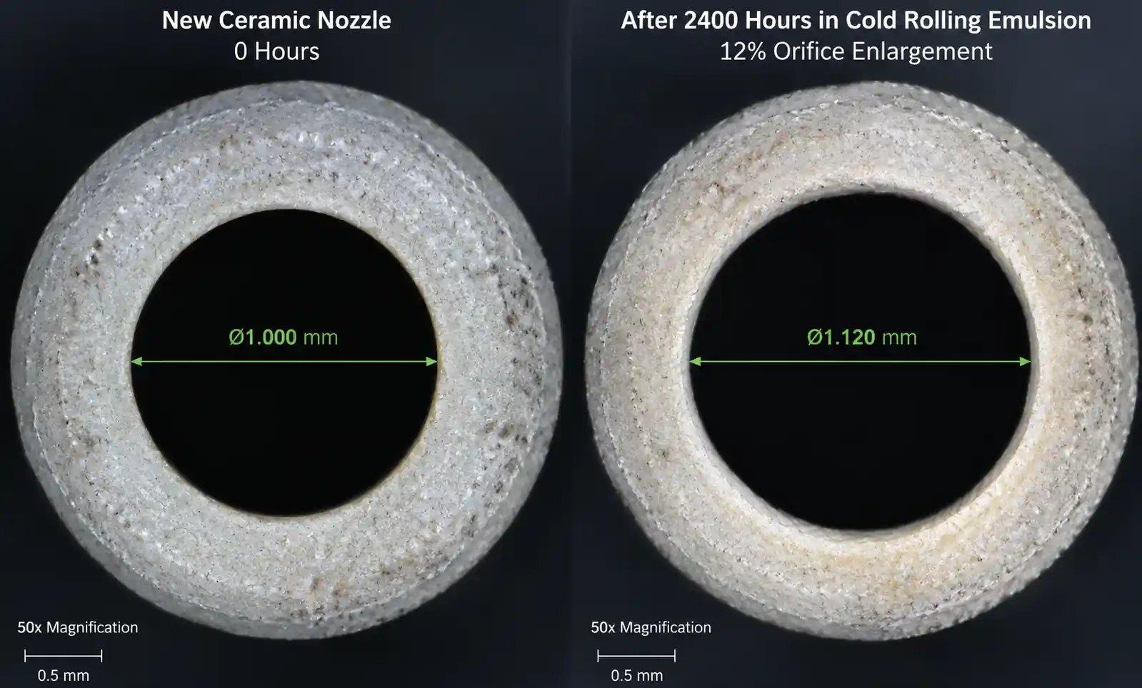
Nozzle wear is the silent killer of flatness control. Unlike catastrophic failure, gradual orifice enlargement and spray pattern distortion occur slowly over hundreds of operating hours, making it difficult to correlate with emerging flatness problems. By the time you notice the defects, your nozzles may be delivering 15–30% more flow than designed, with severely degraded uniformity.
Wear Mechanisms in Cold Rolling Emulsion
Cold rolling emulsions contain fine metallic particles, mill scale fragments, and occasionally abrasive additives. Even at 4–6 bar pressure, these particles erode nozzle orifices over time. The wear rate depends on material hardness, particle concentration, and flow velocity. Brass and stainless steel nozzles may wear out in 200–500 hours in heavily contaminated systems; ceramic and carbide nozzles last 2000–5000 hours in the same conditions.
| Nozzle Material | Typical Hardness | Relative Wear Life | Initial Cost Multiple | Recommended Application |
|---|---|---|---|---|
| Brass | 60–120 HV | 1x (baseline: 300 hrs) | 1x | Clean water systems only |
| 303 Stainless Steel | 160–200 HV | 2–3x (600–900 hrs) | 1.5x | Lightly contaminated emulsion |
| 316 Stainless Steel | 180–220 HV | 3–4x (900–1200 hrs) | 1.8x | Standard cold rolling emulsion |
| Ceramic (Al₂O₃ 95%) | 1200–1500 HV | 8–12x (2400–3600 hrs) | 4–6x | Abrasive emulsion, long service intervals |
| Silicon Carbide (SiC) | 2400–2800 HV | 15–20x (4500–6000 hrs) | 8–12x | Extreme wear environments |
| Tungsten Carbide | 1400–1800 HV | 12–18x (3600–5400 hrs) | 6–10x | Best cost-performance for most mills |
Wear life data from field installations in cold rolling mills with 3–5% emulsion concentration and <50 ppm particle loading at 4–6 bar operating pressure.
Total Cost of Ownership Calculation
The upfront cost difference between stainless steel and ceramic nozzles appears significant—often 4–6x higher. However, when you factor in replacement labor, production interruptions, and flatness defect costs during the degradation period, ceramic and carbide materials deliver lower total cost of ownership in most cold rolling applications.
Consider a typical installation: 40 nozzles per mill stand, 2 stands, requiring 4 hours downtime for complete nozzle changeout. Assuming stainless steel nozzles last 1000 hours and ceramic nozzles last 3000 hours:
- Stainless steel TCO over 3000 hours: 80 nozzles × $25 × 3 changeouts = $6,000 in parts + 12 hours downtime × $8,000/hour = $102,000 total
- Ceramic TCO over 3000 hours: 80 nozzles × $120 × 1 changeout = $9,600 in parts + 4 hours downtime × $8,000/hour = $41,600 total
The ceramic option saves $60,400 over 3000 operating hours—and this calculation excludes the flatness improvement from maintaining consistent spray performance. We recommend tungsten carbide as the optimal balance for most cold rolling applications: 12–15x wear life of stainless steel at 6–8x the cost.
Wear Detection and Replacement Interval
Do not wait for visible failure. Establish a flow testing protocol at 500-hour intervals: remove nozzles, measure flow rate at standard pressure (4 bar), and replace any nozzle showing >8% flow increase from specification. Alternatively, install in-line flow meters on each header and set alarms at +10% total flow deviation. Some mills mark installation dates on each nozzle and replace on a fixed schedule based on the material wear life curve.
7. Installation Configuration: Header Design and Overlap Calculations
Even the highest-quality nozzles will produce poor flatness if installed incorrectly. Spray header design, nozzle spacing, orientation angle, and distance to target all affect coverage uniformity.
Nozzle Spacing and Overlap Calculation
For hydraulic flat fan nozzles, the spray width W at distance D is: W = 2 × D × tan(θ/2), where θ is the spray angle. For uniform coverage, adjacent spray patterns should overlap by 15–25% of their width. Overlap below 10% creates visible striping; overlap above 30% wastes emulsion and can create flow instability.
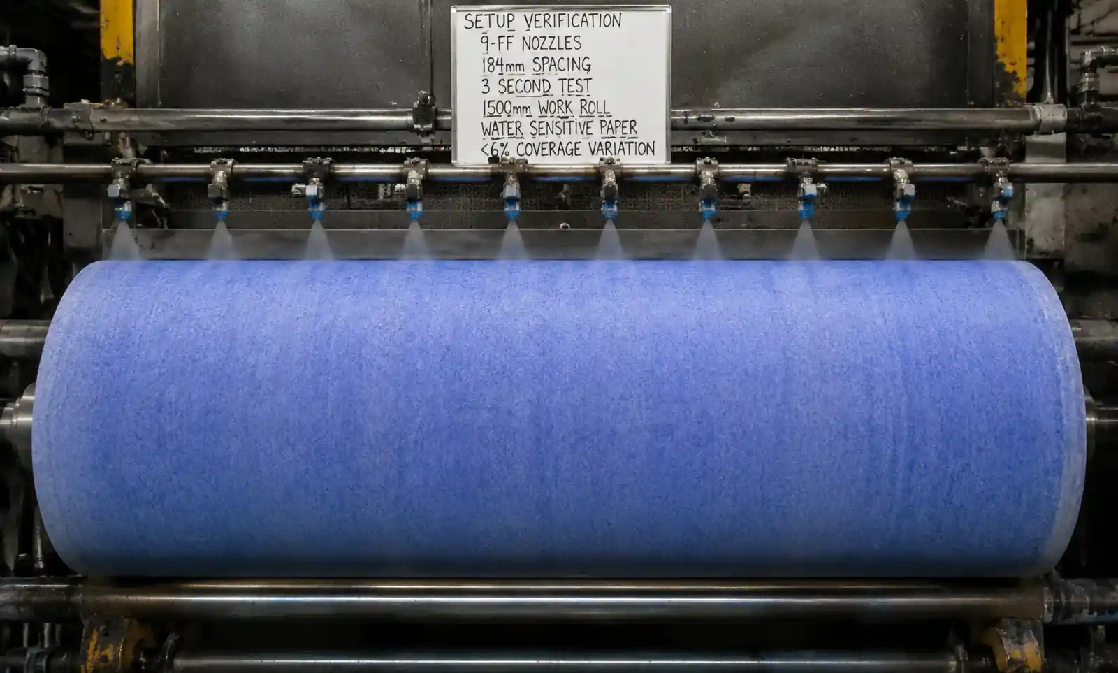
Worked Example:
- Nozzle spray angle: 75°
- Mounting distance to roll surface: 150 mm
- Spray width: W = 2 × 150 × tan(75°/2) = 2 × 150 × tan(37.5°) = 2 × 150 × 0.7673 = 230 mm
- Target overlap: 20%
- Effective coverage per nozzle: 230 × (1 - 0.20) = 184 mm
- Nozzle spacing: 184 mm center-to-center
For a 1500 mm roll barrel length, this requires 1500/184 = 8.15 → 9 nozzles per header (round up to ensure full coverage at edges).
Verify your design using water-sensitive paper tests: mount paper on the roll surface, spray for 2–3 seconds, and measure the coverage intensity across the width. Coefficient of variation should be below 8%.
Orientation Angle and Impingement
Mount nozzles perpendicular to the roll surface for maximum impact force and film formation. Angled mounting (>15° off-normal) reduces effective pressure and creates asymmetric coverage. If space constraints require angled mounting, compensate by reducing nozzle spacing by 10–15% to maintain overlap.
Header Pressure Drop and Flow Balancing
Supply headers must maintain pressure uniformity across all nozzles. If your header is undersized, nozzles nearest the inlet receive higher pressure and flow more emulsion, creating non-uniform coverage. Use the simplified pressure drop formula: ΔP ≈ (8 × f × L × Q²) / (π² × D⁵), where f is friction factor, L is header length, Q is total flow, and D is header inner diameter.
Practical guideline: header velocity should not exceed 3 m/s, and pressure drop from inlet to furthest nozzle should be below 5% of nozzle operating pressure. For an 8-nozzle header at 4 bar nozzle pressure, maximum acceptable header ΔP is 0.2 bar. If measured pressure drop exceeds this, increase header diameter or switch to center-feed configuration.
Common Installation Mistakes
From field audits of 30+ cold rolling mills, we identified recurring installation errors that degrade flatness control:
- Nozzle spacing based on visual appearance rather than calculated overlap: Results in 12–18% coverage variation.
- Mounting distance outside the optimal range: Most hydraulic flat fans are calibrated for 100–200 mm distance; mounting at 300 mm increases sensitivity to pressure variation and spray angle wear.
- Using pipe thread sealant that migrates into nozzle passages: Teflon tape fragments are a common clogging cause—use liquid thread sealant rated for your emulsion chemistry.
- No flow balancing between headers: In tandem mills, each stand must receive identical flow; 10% variation between stands creates systematic flatness errors.
- Ignoring spray orientation during nozzle replacement: Even a 5° rotation during installation shifts the spray pattern and disturbs overlap.
8. Troubleshooting Flatness Defects Linked to Nozzle Performance
When flatness problems emerge after extended production runs or coincide with emulsion system maintenance, suspect nozzle degradation or configuration changes. Use this diagnostic approach to isolate spray-related causes.
| Flatness Defect Pattern | Possible Nozzle-Related Cause | Diagnostic Test | Corrective Action |
|---|---|---|---|
| Center buckle developing gradually over days | Worn center nozzles delivering excess flow; thermal crown increase | Flow test all nozzles at 4 bar; plot flow vs position | Replace nozzles showing >10% flow increase; verify center-to-edge flow variation <5% |
| Edge wave on one side only | Single header clogged or header pressure drop excessive on one side | Measure header pressure at inlet and end; check individual nozzle flow | Clear clogged header; increase header diameter if ΔP >5% |
| Quarter buckle after emulsion concentration adjustment | Changed surface tension altering droplet size and film formation | Measure Dv0.5 with laser diffraction at current concentration vs baseline | Return to baseline concentration; if concentration change is required, adjust nozzle pressure to restore droplet size |
| Intermittent flatness variation correlating with coil changes | Emulsion flow pulsation from pump or pressure regulation instability | Install pressure gauge at header; record during rolling | Add accumulator or upgrade pressure regulator; stabilize supply pressure to ±2% |
| Flatness deterioration after nozzle replacement | Incorrect nozzle type/angle installed, or spacing changed | Water-sensitive paper coverage test; verify nozzle part numbers vs design | Reinstall correct nozzles; re-verify spacing and orientation |
| Progressive flatness degradation over 1000+ operating hours | Nozzle wear enlarging orifices and narrowing spray angle | Spray angle measurement using protractor and spray visualization; flow test | Replace all nozzles in affected header; implement 500-hour inspection interval |
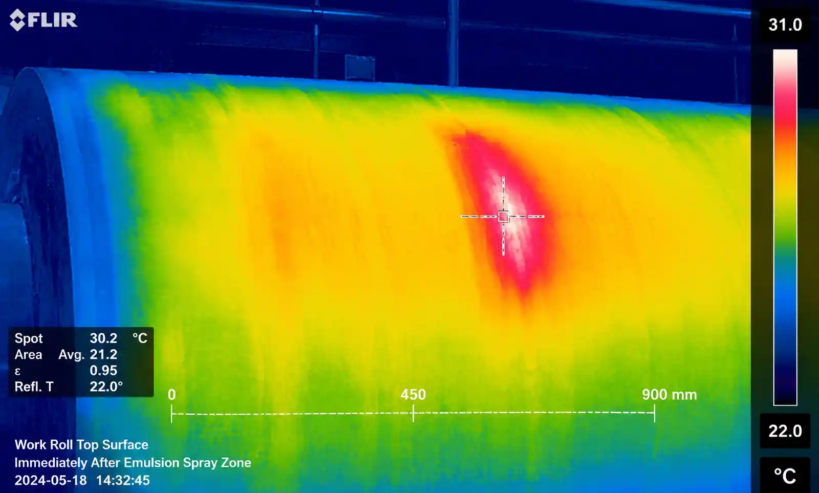
Advanced Diagnostic: Thermal Imaging
For persistent flatness issues with unclear cause, use infrared thermal imaging to map roll surface temperature distribution immediately after the emulsion spray zone. Temperature variation above ±4°C indicates non-uniform cooling, which directly correlates with coverage variation. We identified a case where thermal imaging revealed a 9°C hot spot corresponding to a nozzle with a partially clogged orifice—flow testing alone showed only 6% reduction, but spray pattern was severely distorted.
Preventive Maintenance Schedule
Based on field reliability data, we recommend this maintenance cadence for cold rolling emulsion nozzles:
- Weekly: Visual inspection for leaks and clogging
- Every 500 hours: Flow test all nozzles; replace any showing >8% deviation from specification
- Every 1000 hours (stainless steel) / 2000 hours (ceramic/carbide): Complete nozzle replacement regardless of flow test results (spray angle and pattern degrade before flow increases significantly)
- After any emulsion chemistry change: Coverage verification using water-sensitive paper
- Following unplanned mill shutdowns: Check for debris in headers and nozzle blockage
9. FAQ
Q: Can I mix nozzle materials in the same header to reduce cost?
We do not recommend this approach. Mixed materials wear at different rates, creating progressive flow imbalances that are difficult to track. If cost is a constraint, use stainless steel for all nozzles and accept more frequent replacement, or use ceramic/carbide throughout and extend intervals. The one exception: you can use more wear-resistant materials in center positions where particle concentration is typically higher due to flow patterns.
Q: How much flow variation across nozzles is acceptable?
For flatness-critical applications, maintain flow variation (coefficient of variation) below 5% across all nozzles in a header. This corresponds to roughly ±10% from mean flow. Above 12% CV, you will see measurable flatness impact. Test this by measuring individual nozzle flow at your standard operating pressure.
Q: Does spray impingement angle affect flatness?
Yes, significantly. Off-normal angles (>15° from perpendicular) reduce effective impact pressure and create asymmetric coverage. If you must angle nozzles due to space constraints, keep the angle below 20° and reduce nozzle spacing by 15% to compensate for the distorted spray pattern.
Q: Can I increase pressure to compensate for worn nozzles?
Short-term yes, but this is not a solution. Raising pressure does increase flow, but only by the square root of the pressure ratio—and you simultaneously narrow the spray angle and shift droplet size distribution. We have seen mills raise pressure from 4 bar to 9 bar trying to restore coverage, but spray angle narrowed from 75° to 65°, actually making uniformity worse.
Q: How do I know if my flatness problem is spray-related versus mechanical?
Compare flatness behavior immediately after nozzle replacement to behavior after 800–1000 operating hours. If flatness improves significantly after nozzle service, the spray system was contributing. Additionally, spray-related flatness issues often show gradual onset over weeks, while mechanical issues (roll bearing wear, mill deformation) tend to appear more suddenly or show consistent patterns regardless of maintenance timing.
Q: Should I use strainers or filters upstream of nozzles?
Absolutely. Install 100-mesh (150 micron) or finer strainers immediately upstream of each header. This protects nozzles from debris and extends wear life. Clean or replace strainers every 200 hours or when pressure drop across the strainer exceeds 0.3 bar. Do not over-filter (below 50 micron)—this creates excessive pressure drop and flow restriction.
10. Conclusion
Flatness control in cold rolling is a system problem, and the emulsion spray system is a first-order contributor. Nozzle selection is not a commodity purchasing decision—it is an engineering specification that directly affects product quality, scrap rate, and mill productivity.