



Preventing 'Wet Wall' Phenomenon in SCR Denitrification Systems: How to Avoid Flue Gas Corrosion Through Nozzle Angle (2026)
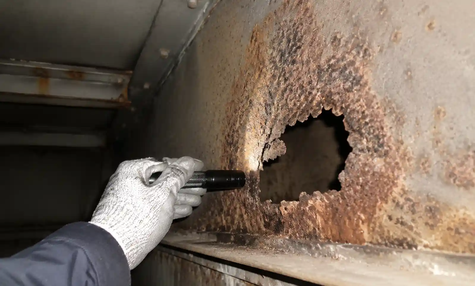
SCR system operators know the problem well: liquid ammonia or urea hits the duct wall before it evaporates, and suddenly you're looking at ammonium bisulfate corrosion eating through 3-5mm of carbon steel per year. Based on field assessments across 40+ power plants, wet wall corrosion costs $150,000-$400,000 per 500 MW unit over five years in unplanned repairs. The fix starts with nozzle angle.
Table of Contents
- 1. 1. Understanding Wet Wall Phenomenon
- 2. 2. Critical Spray Parameters for SCR
- 3. 3. Nozzle Angle Selection Guide
- 4. 4. Material Selection and Corrosion Protection
- 5. 5. Installation and Validation
- 6. 6. Troubleshooting
- 7. 7. FAQ
- 7.1. Can I retrofit wider spray angle nozzles to improve NOx distribution without causing wet wall?
- 7.2. What's the minimum flue gas temperature to avoid wet wall with aqueous ammonia injection?
- 7.3. How do I calculate the economic breakeven between air-assist and hydraulic nozzles?
- 7.4. Can wet wall occur even with proper nozzle angle selection?
- 7.5. How often should I replace SCR injection nozzles?
- 7.6. What's the fastest way to identify which nozzle is causing wet wall?
- 7.7. Does spray angle change with nozzle wear?
- 8. 8. Conclusion
1. Understanding Wet Wall Phenomenon
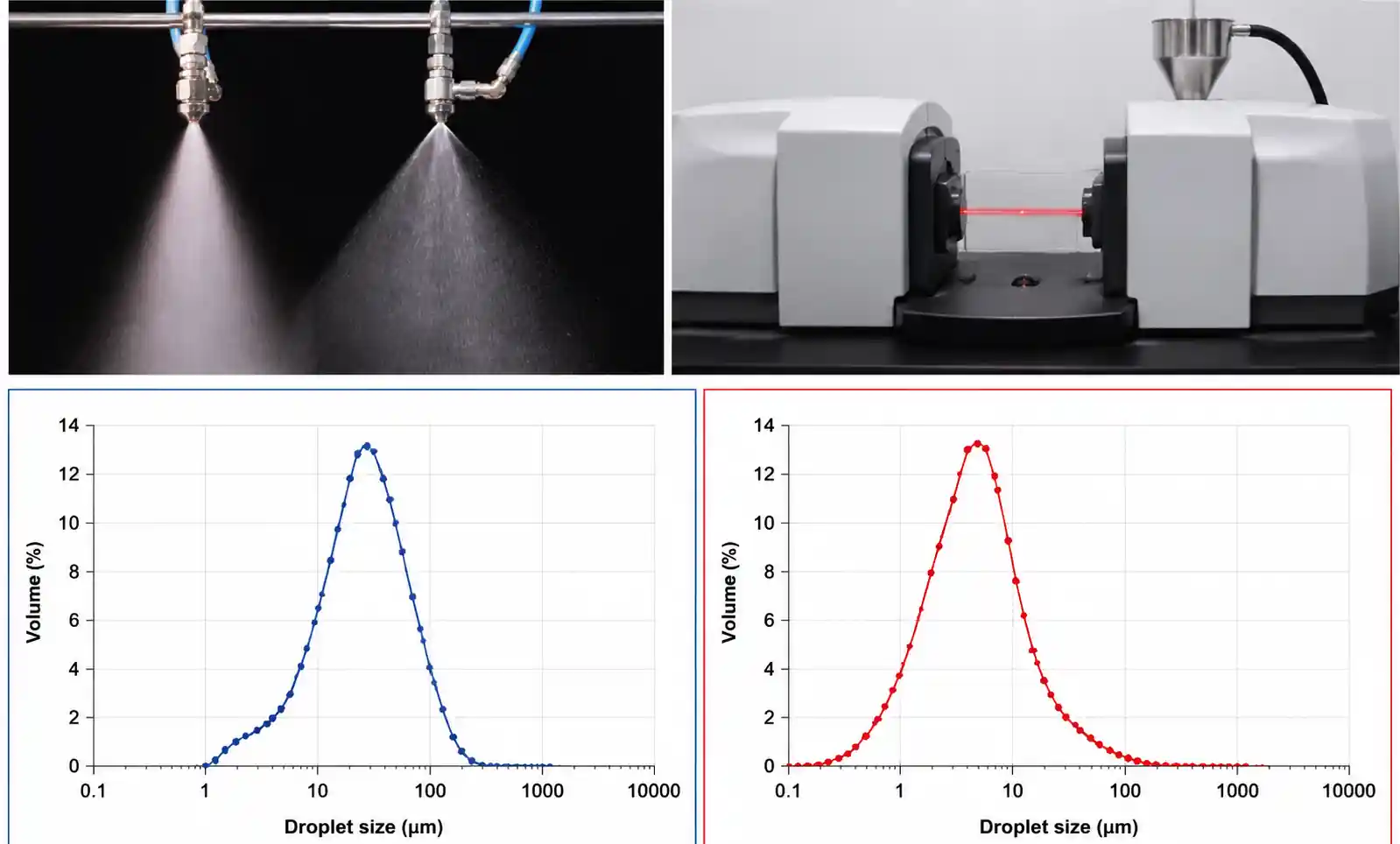
Wet wall happens when the evaporation distance of injected droplets exceeds the available clearance to the duct wall. Evaporation distance depends on droplet size, flue gas temperature, velocity, and ammonia concentration. In typical 25% ammonia solution at 350°C with 8 m/s gas velocity, droplets larger than 150 microns need over 1.2 meters to evaporate fully. If your spray pattern projects droplets toward a wall within that distance, you'll get corrosion.
Once liquid hits the wall, ammonium bisulfate forms at 200-320°C: NH₃ + SO₃ + H₂O → NH₄HSO₄
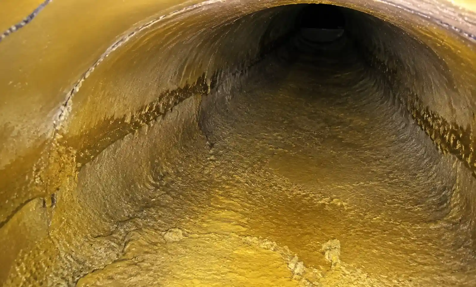
This creates a sticky, acidic layer (pH 1-2) that traps sulfur compounds, prevents protective oxide formation, and accelerates pitting. Carbon steel ducts lose 2-4 mm/year in ABS-affected zones; 304 stainless loses 0.5-1.2 mm/year.
2. Critical Spray Parameters for SCR
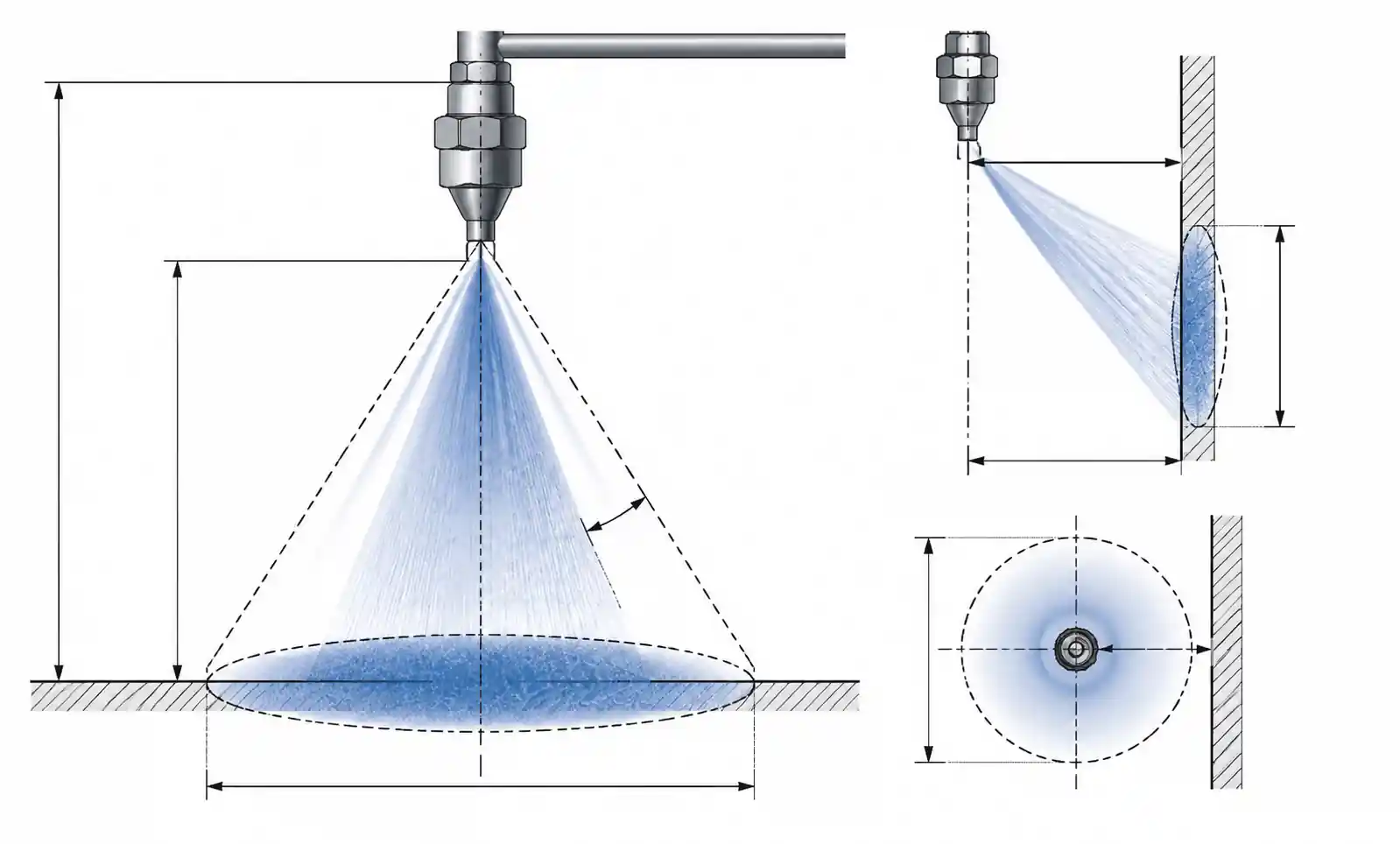
The fundamental constraint is ensuring the spray cone never hits duct walls before evaporation completes. For a nozzle at distance D from the wall with spray angle θ:
Minimum clearance (Cmin) = D × tan(θ/2) + safety margin
Safety margin should be at least 200mm—spray drift, nozzle wear, and pressure fluctuations will eat into your clearance.
| Duct Configuration | Spray Angle Range | Nozzle Type | Wall Clearance Required |
|---|---|---|---|
| Large rectangular (>3m width) | 60-80° | Hollow cone, air-assist | 800-1200mm |
| Medium rectangular (1.5-3m) | 40-60° | Flat fan, hollow cone | 500-800mm |
| Circular duct (<2m diameter) | 20-40° | Narrow flat fan, solid cone | 300-500mm |
| Lance insertion (confined) | 15-30° | Solid stream, narrow cone | 150-300mm |
In retrofits with limited clearance, reducing spray angle is your primary adjustment. A 60° nozzle at 0.5m from the wall projects 433mm horizontally—if evaporation distance is 800mm, you're going to get wet wall.
Droplet size trade-off: Smaller droplets evaporate faster but require more pressure or air-assist. At 350°C and 8 m/s:
- 50 microns → 400mm evaporation (air-assist, +$15k/year in compressed air)
- 100 microns → 800mm (hydraulic at 20 bar, standard)
- 150 microns → 1200mm (hydraulic at 8 bar, risky)
Air-assist works for tight installations but adds $8,000-15,000/year in compressed air costs per 500 MW unit.
For a broader perspective on how droplet size optimization applies across different industrial applications—from dust suppression to gas cooling—see our Industrial Spray Dust Suppression Systems & Nozzles guide for detailed specifications on droplet size selection and material durability in demanding environments.
3. Nozzle Angle Selection Guide
Step 1: Measure available clearance — distance from injection point to nearest wall, opposite wall, and vertical limits.
Step 2: Determine evaporation distance — calculate Dv0.5 at operating pressure, estimate evaporation distance, add 30% safety factor for wear and variation.
Step 3: Calculate maximum spray angle
θmax = 2 × arctan[(Dwall - Devap - 200mm) / L]
Step 4: Select nozzle with θ ≤ θmax
Worked example—retrofit:
- Duct: 2.4m × 3.0m, lance extends 0.6m from side wall
- Clearance to opposite wall: 1.8m
- Evaporation distance for 100 micron droplets at 360°C, 9 m/s: 0.85m
- Safety margin: 0.2m
- Available spray projection: 1.8 - 0.85 - 0.2 = 0.75m
- tan(θ/2) = 0.75 / 1.5 (mixing length) → θmax ≈ 53°
Select: 50° hollow cone at 15 bar, producing 90-110 micron droplets. This gives you margin for wear while keeping droplets off the wall.
4. Material Selection and Corrosion Protection
Even with correct angle selection, transient wet wall events happen during startups, load swings, or plugging. Material choice is your backup.
| Material | Hardness (HRC) | ABS Corrosion Rate | Abrasion Resistance | Cost Factor | Best For |
|---|---|---|---|---|---|
| 316L SS | 18-22 | 0.3 mm/yr | Moderate | 1.0× | Clean flue gas, standard service |
| Hastelloy C-276 | 20-25 | <0.1 mm/yr | Moderate | 8-12× | High-sulfur coal, wet wall risk |
| Silicon Carbide | 65-70 | <0.05 mm/yr | Excellent | 15-20× | Abrasive ash, long intervals |
| Tungsten Carbide | 70-75 | <0.08 mm/yr | Excellent | 10-15× | High wear + corrosion |
The same material economics apply across industrial spraying applications—tungsten carbide and silicon carbide inserts consistently deliver superior ROI in abrasive service. For detailed material economics and ROI analysis in high-pressure cleaning applications, see our High Pressure Tank Cleaning Nozzle Selection Guide 2026: Rotary vs Static vs Orbital.
Economics: 500 MW unit with 24 nozzles in high-sulfur coal service—SiC nozzles ($1,800 each) last 4-5 years versus 316SS ($180 each) needing replacement every 12-18 months. SiC TCO is 35% lower over 10 years when you factor in labor and downtime.
Duct liner protection when geometry forces marginal angles:
- Hastelloy C-276 panels (3mm): 8-12 year protection, $120-180/m²
- Refractory coating: 5-7 years, $80-120/m²
- Inconel 625 overlay: permanent but $200-300/m²
5. Installation and Validation
Never trust calculated spray patterns—always validate.
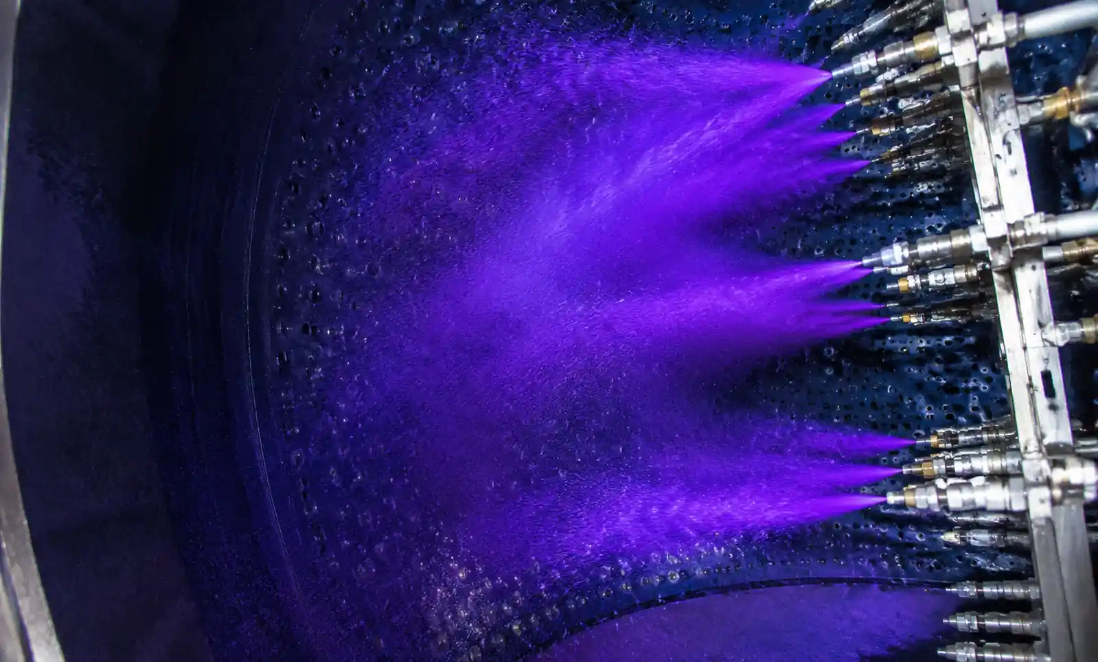
Cold water spray test: Run water at operating pressure, use UV light or water-sensitive paper to verify no wall contact.
Hot commissioning: With flue gas at operating temperature, inject water and verify complete evaporation.
Actual spray angles vary ±8° from catalog values—manufacturing tolerances, installation alignment errors, and supply pressure variations all contribute.
Alignment tolerances (non-negotiable):
| Parameter | Tolerance | Impact if Exceeded | Validation Method |
|---|---|---|---|
| Insertion depth | ±10mm | Spray centerline shifts 50-100mm | Physical measurement |
| Angle to duct axis | ±3° | Wall clearance reduces 100-200mm per meter | Laser alignment |
| Rotation (clock) | ±5° | Adjacent nozzle interference | Visual + protractor |
Documented cases where 5-8° misalignment caused wet wall corrosion within six months despite theoretically adequate design margins.
6. Troubleshooting
Early indicators:
- White/yellow-brown deposits on duct walls near injection zone
- Cold spots 20-30°C below bulk gas temperature
- Ammonia slip increase (nozzle plugging distorting pattern)
- Pressure drop increase of 5-10%
| Symptom | Most Likely Cause | Diagnostic | Fix |
|---|---|---|---|
| Deposits directly downstream | Spray angle too wide | Water spray test | Replace with narrower nozzles |
| Deposits on one side only | Misalignment or plugging | Flow measurement per nozzle | Realign or clean/replace |
| Intermittent deposits | Load swings/temperature excursions | Data logging | Add temperature compensation |
| Progressive worsening | Nozzle wear enlarging orifice | Flow test at constant pressure | Replace (18-24 month interval) |
For a broader understanding of how nozzle selection impacts coverage consistency and maintenance intervals across different cleaning applications, see our Rotary Tank Cleaning Nozzle Selection Guide 2026: Free-Spinning vs Controlled Rotation for detailed coverage and lifecycle analysis.
Preventive schedule for coal-fired applications:
- Monthly: Visual inspection (if accessible)
- Quarterly: Flow verification
- Annually: Remove and inspect
- 18-24 months: Replace standard 316SS (extend to 36-48 months for carbide/ceramic)
7. FAQ
Can I retrofit wider spray angle nozzles to improve NOx distribution without causing wet wall?
Only if you simultaneously increase injection pressure to reduce droplet size and shorten evaporation distance, or add air-assist atomization. Verify with CFD modeling or water spray test before implementing. Wider angle alone will almost certainly make wet wall worse.
What's the minimum flue gas temperature to avoid wet wall with aqueous ammonia injection?
Minimum 300°C for 25% ammonia with standard hydraulic nozzles. Below 280°C, consider switching to anhydrous ammonia or adding duct heaters. Droplets won't evaporate fast enough below these temperatures regardless of angle.
How do I calculate the economic breakeven between air-assist and hydraulic nozzles?
Air-assist adds $10,000-18,000/year in compressed air costs per 500 MW unit but may eliminate $80,000-150,000 in duct repair costs over five years if geometry constraints make hydraulic injection risky. Payback is typically 8-18 months in retrofit applications with tight clearances.
Can wet wall occur even with proper nozzle angle selection?
Yes. Load swings reduce flue gas temperature below design minimum, startup/shutdown conditions, or nozzle plugging distorting spray pattern. Design for worst-case transient conditions, not just steady-state operation.
How often should I replace SCR injection nozzles?
In coal-fired service with 316SS nozzles, plan replacement at 18-24 months. Switch to carbide/ceramic and extend to 36-48 months. The TCO analysis almost always favors premium materials if you're paying for labor and outage time.
What's the fastest way to identify which nozzle is causing wet wall?
Water spray test during outage. Run water at operating pressure, mark wall contact areas, trace back to the nozzle that's projecting beyond the safe zone. Works every time.
Does spray angle change with nozzle wear?
Yes—orifice enlargement changes the exit velocity profile and typically increases spray angle by 5-10° before flow increase becomes obvious. This is why annual inspection catches issues that quarterly flow testing alone might miss.
8. Conclusion
Preventing wet wall corrosion comes down to three things: accurate clearance measurement, validated evaporation distances, and sufficient safety margin. Measure the duct. Calculate the spray angle. Then validate with water before you inject ammonia.
For detailed nozzle angle calculations for your specific SCR configuration, contact application engineering with your duct dimensions, flue gas conditions, and reagent specs.