



Optimizing Spray Coverage: Pattern and Spacing Calculations
Achieving uniform spray coverage requires precise nozzle spacing calculations based on spray angle, mounting height, and overlap percentage. The industry standard is 50% overlap between adjacent spray patterns, calculated using the formula: Spacing = 2 × Height × tan(Angle/2) × Overlap Factor. Proper coverage optimization reduces chemical waste by 20-30%, eliminates streaking, and ensures consistent application across industrial processes from coating to cooling systems.
Table of Contents
- 1. Understanding Spray Coverage Fundamentals
- 2. Critical Variables in Coverage Calculations
- 3. Nozzle Spacing Calculation Methods
- 4. Overlap Percentage and Pattern Uniformity
- 5. Mounting Height Determination
- 6. Spray Pattern Types and Coverage Characteristics
- 7. Verification and Testing Methods
- 8. Common Coverage Problems and Solutions
- 9. FAQ
- 10. Conclusion
Understanding Spray Coverage Fundamentals
Spray coverage optimization is the engineering discipline of positioning nozzles to deliver uniform liquid distribution across a target surface. Poor coverage creates gaps, streaks, and inconsistent application that waste materials and compromise process quality.
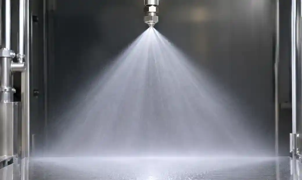 Industrial spray nozzle coverage pattern showing geometric distribution principles
In fifteen years of optimizing spray systems across manufacturing facilities, I've seen coverage failures cost companies thousands in rejected product and chemical waste. The root cause is almost always miscalculated nozzle spacing or incorrect mounting heights. Getting coverage right from the start eliminates these losses.
The coverage area of a single nozzle follows geometric principles. For flat fan nozzles, the spray forms an elliptical pattern. Full cone nozzles produce circular coverage. Hollow cone nozzles create ring patterns with concentrated flow at the edges. Understanding these pattern geometries is essential for accurate spacing calculations.
Critical Variables in Coverage Calculations
Four variables control spray coverage outcomes:
Spray Angle: The cone or fan angle determines pattern width at any given distance. Standard angles range from 15° to 120°. Narrow angles (25-40°) provide concentrated impact and longer reach. Wide angles (80-120°) deliver broad coverage at shorter distances. Spray angle is fixed by nozzle design and cannot be adjusted in the field.
Mounting Height: The distance between the nozzle orifice and target surface. Greater height produces wider coverage but reduces impact force and droplet density. Typical industrial mounting heights range from 300mm to 1500mm depending on application requirements.
Overlap Percentage: The degree to which adjacent spray patterns intersect. Industry standard is 50% overlap for uniform distribution, though some applications use 30-70% depending on uniformity requirements and nozzle pattern characteristics.
Operating Pressure: While pressure primarily affects flow rate and droplet size, it also influences spray angle. Most nozzles are rated at specific pressures (2-4 bar typical). Operating significantly above or below rated pressure changes the spray angle by 5-15%, affecting coverage calculations.
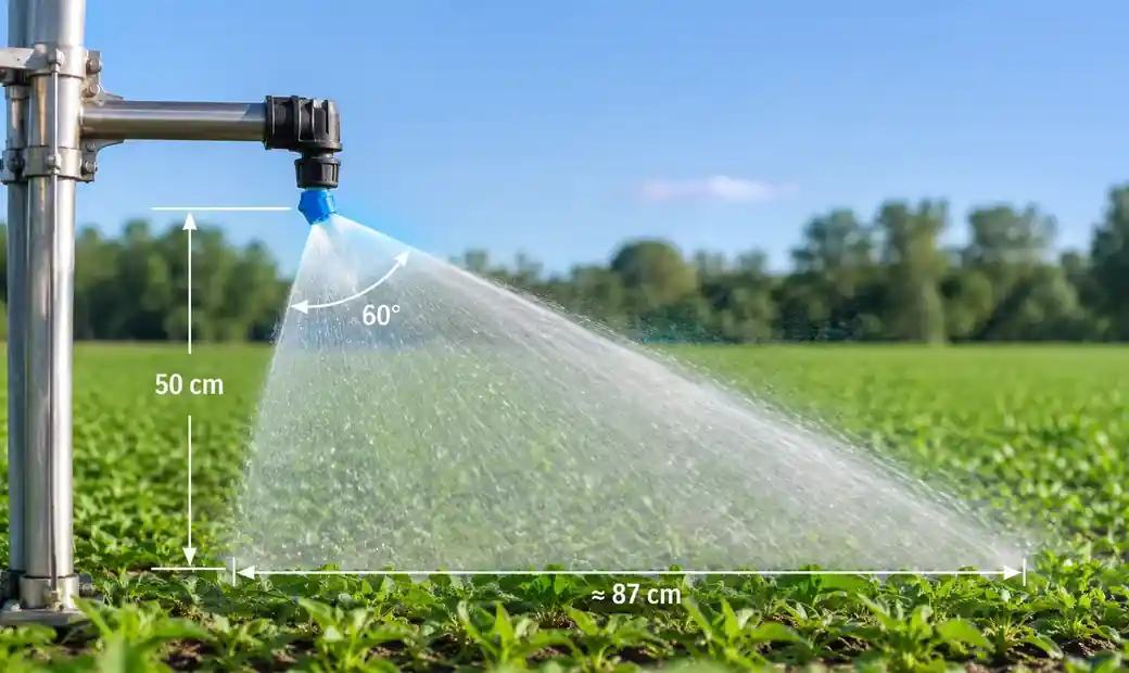 Diagram showing relationship between spray angle and mounting height for coverage calculations
Nozzle Spacing Calculation Methods
The fundamental spacing formula for flat fan and cone nozzles is:
Spacing (S) = 2 × Height (H) × tan(Angle/2) × Overlap Factor (OF)
Where:
- S = center-to-center distance between nozzles
- H = mounting height from nozzle to target
- Angle = spray angle in degrees
- OF = overlap factor (0.5 for 50% overlap, 0.6 for 40% overlap, 0.4 for 60% overlap)
Practical Example: A flat fan nozzle with 80° spray angle mounted at 600mm height with 50% overlap:
S = 2 × 0.6m × tan(40°) × 0.5 S = 2 × 0.6m × 0.839 × 0.5 S = 0.503m or 503mm spacing
This calculation ensures adjacent spray patterns meet at their half-width points, creating uniform distribution according to established agricultural engineering standards.
| Spray Angle | Height 400mm | Height 600mm | Height 800mm | Height 1000mm |
|---|---|---|---|---|
| 40° | 298mm | 447mm | 596mm | 745mm |
| 65° | 457mm | 686mm | 914mm | 1143mm |
| 80° | 503mm | 755mm | 1006mm | 1258mm |
| 110° | 597mm | 895mm | 1194mm | 1492mm |
Table 1: Recommended nozzle spacing at 50% overlap for common spray angles. Based on YuechenPrecision Technology field testing data.
For circular coverage patterns like full cone nozzles, calculate the effective diameter and arrange in square or triangular grid patterns for optimal coverage.
Overlap Percentage and Pattern Uniformity
Overlap percentage directly impacts distribution uniformity measured by Coefficient of Variation (CV). Lower CV values indicate more uniform coverage.
Research from MDPI Process Engineering studies shows that a 0.1m increase in nozzle spacing reduces peak overlap flow by approximately 30% and overlap width by 40%. This demonstrates how critical precise spacing is to uniformity.
50% Overlap: Industry standard for most applications. Provides CV values of 10-15% with quality nozzles. Each nozzle's edge meets the adjacent pattern's edge, creating consistent coverage.
30-40% Overlap: Used where slight variation is acceptable and wider spacing reduces nozzle count and costs. Typical CV of 15-20%. Common in dust suppression and cooling applications.
60-70% Overlap: Required for critical applications demanding CV below 10%, such as coating, printing, and chemical processing. Higher nozzle density increases system cost but ensures precision uniformity.
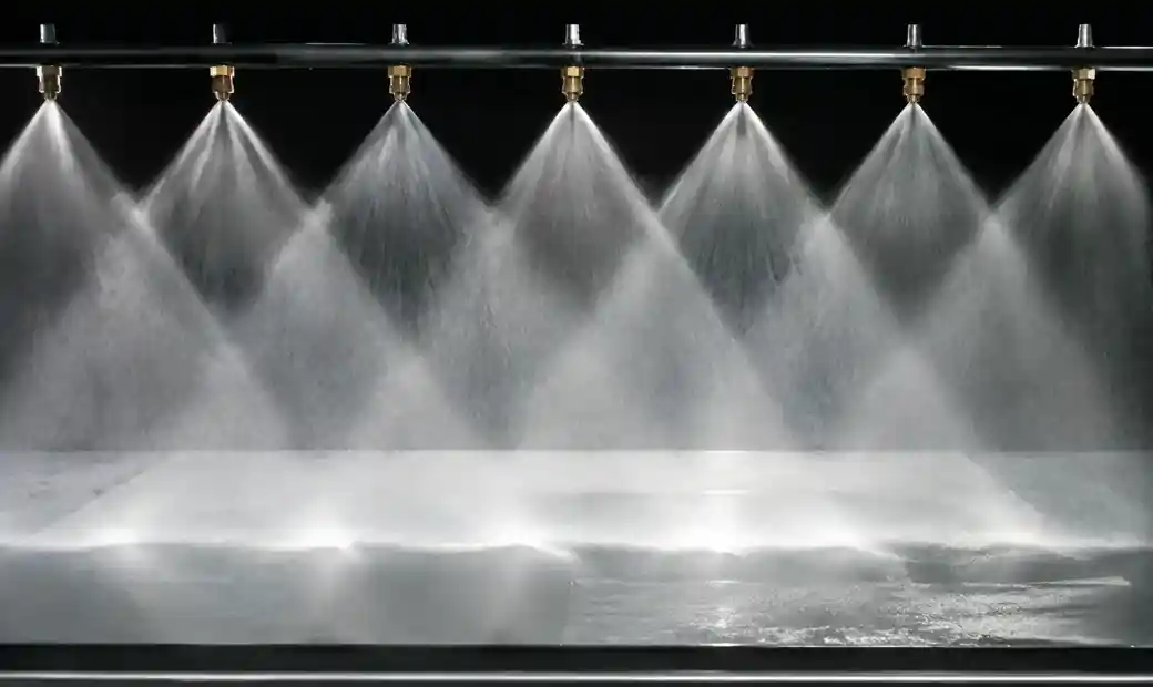 Spray nozzle overlap patterns demonstrating uniform distribution coverage
Pattern distribution is not uniform across the spray width. Most nozzles produce bell-curve or trapezoidal distributions. Proper overlap compensates for weaker edge flow by combining the strong center of one pattern with the weak edge of the adjacent pattern.
| Overlap % | Typical CV | Nozzle Count (10m width) | Application Examples |
|---|---|---|---|
| 30% | 18-22% | Fewer nozzles | Dust suppression, general washing |
| 50% | 10-15% | Standard density | Coating, chemical application, cooling |
| 70% | 7-12% | Higher density | Precision coating, printing, pharmaceutical |
Table 2: Overlap percentage impact on uniformity and system design. Data from YuechenPrecision Technology application testing.
Mounting Height Determination
Mounting height balances coverage width against impact force and droplet integrity. Optimal height depends on spray angle, target area dimensions, and application requirements.
Height Calculation from Required Spacing: When spacing is fixed by existing equipment, reverse the formula to find required height:
Height (H) = Spacing (S) / (2 × tan(Angle/2) × OF)
Example: Fixed 800mm nozzle spacing with 65° spray angle requiring 50% overlap:
H = 800mm / (2 × tan(32.5°) × 0.5)
H = 800mm / (2 × 0.637 × 0.5)
H = 800mm / 0.637
H = 1256mm mounting height required
 Industrial nozzle mounting height measurement for coverage optimization
Height Constraints:
Too Low: Insufficient coverage width requires excessive nozzle density. Creates hot spots where patterns don't overlap. Common in retrofit installations where ceiling height limits options.
Too High: Droplets lose velocity before reaching target. Wind drift increases. Evaporation losses rise in humidification and cooling systems. Fine sprays may not reach the surface at all.
For industrial applications, I recommend maintaining heights between 0.5m and 1.5m for most spray nozzle systems. This range provides manageable coverage widths while maintaining droplet integrity and impact force.
Spray Pattern Types and Coverage Characteristics
Different nozzle types produce distinct patterns requiring specific spacing approaches:
Flat Fan Patterns: Produce elliptical coverage with tapered edges. Designed for overlap—never use in single-pass applications. Standard spacing calculation applies. Flat fan nozzles excel in linear conveyor systems, surface washing, and coating lines.
Full Cone Patterns: Create circular coverage with uniform distribution throughout the cone. Square or triangular grid arrangements work best for area coverage. Calculate diameter at target height, then space at diameter × overlap factor. Excellent for gas scrubbing and cooling applications.
Hollow Cone Patterns: Concentrate flow at pattern edges with minimal center volume. Require different overlap calculations because the active spray region is ring-shaped. Hollow cone designs provide superior atomization for fire suppression and chemical processing.
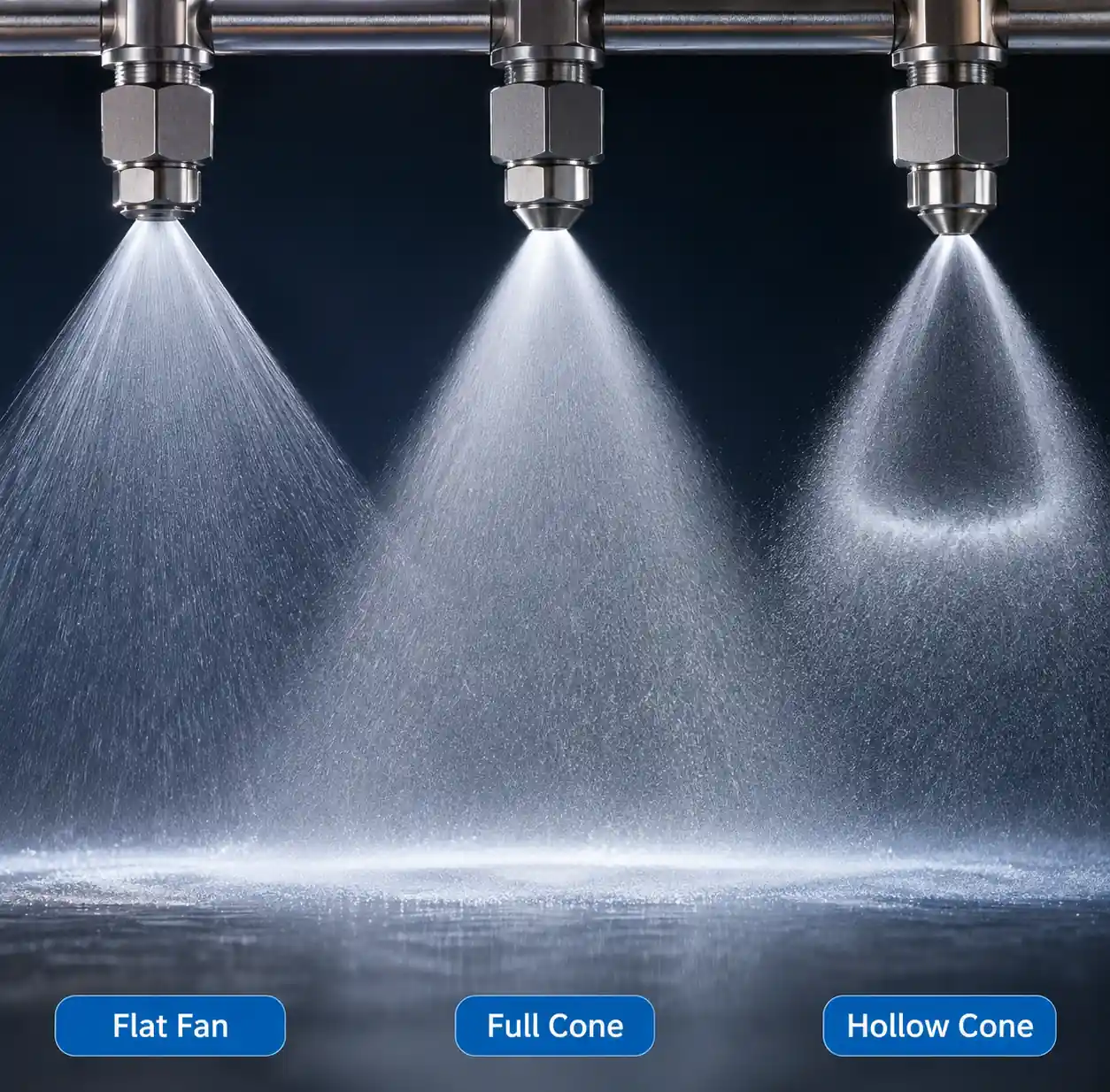 Comparison of flat fan, full cone, and hollow cone spray patterns
Air Atomizing Patterns: Produce fine fog with indistinct pattern boundaries. Coverage depends on air pressure, liquid flow rate, and distance. Require empirical testing rather than geometric calculations for optimal spacing.
Pattern integrity degrades with distance. What starts as a well-defined 80° fan at 200mm becomes diffuse and irregular at 1500mm. Always verify actual coverage patterns at your operating conditions, not just manufacturer's specifications.
Verification and Testing Methods
Coverage calculations provide starting points—field verification confirms actual performance. Three testing methods validate coverage uniformity:
Water-Sensitive Paper Test: Place yellow paper strips across the coverage area perpendicular to spray direction. Water droplets leave blue marks. Uniform blue density indicates good coverage. Gaps or streaks show spacing problems. Simple and visual but qualitative only.
Collection Pan Method: Place equal-sized collection containers at regular intervals across the spray width. Run the system for a fixed time period. Measure collected volume in each container. Calculate CV from the volumes. CV below 15% indicates acceptable uniformity. This is the standard agricultural calibration method.
 Collection pan method for spray coverage uniformity testing
Flow Rate Verification: Measure actual flow rate from each nozzle at operating pressure. Variation exceeding 10% between nozzles indicates wear, clogging, or pressure inconsistencies that will create coverage problems regardless of spacing calculations. Replace or clean affected nozzles before optimizing spacing.
Digital Spray Patternation: Advanced facilities use spray pattern analyzers that measure droplet distribution and calculate uniformity coefficients directly. These systems provide precise CV measurements and identify pattern distortions. Standard equipment for coating and pharmaceutical applications requiring documented uniformity.
I've found the collection pan method provides the best balance of accuracy and practicality for industrial installations. Use at least 8-10 collection points across one nozzle spacing interval for reliable data.
Common Coverage Problems and Solutions
Problem: Streaking or striping in coverage Root Cause: Insufficient overlap between adjacent patterns. Spacing too wide for the mounting height and spray angle. Solution: Reduce nozzle spacing by 15-20% or increase mounting height following the spacing formula. Verify nozzles produce symmetric patterns—worn orifices create asymmetric patterns that won't overlap correctly.
Problem: Excessive coverage overlap causing dripping or flooding Root Cause: Spacing too tight, creating more than 70% overlap. Common when retrofitting nozzles without recalculating spacing. Solution: Increase spacing or reduce flow rate. If spacing is fixed, select nozzles with narrower spray angles to reduce overlap.
Problem: Coverage varies along spray line Root Cause: Pressure drop across manifold creates flow variation between first and last nozzles. Nozzles at line end receive lower pressure and produce narrower patterns. Solution: Use proper manifold sizing—diameter should maintain velocity below 1.5 m/s. Install pressure gauges at line ends to verify <10% pressure drop. Consider center-feed manifold design for long runs.
 Spray nozzle manifold showing proper pressure distribution setup
Problem: Pattern distortion at edges of coverage area Root Cause: End nozzles lack adjacent patterns to blend with. Creates weak coverage at system boundaries. Solution: Extend nozzle line beyond the required coverage area by one nozzle spacing on each end, or position end nozzles at half-spacing distance from the edge.
Problem: Coverage degrades over time
Root Cause: Nozzle wear enlarges orifices, changing flow rates and spray angles. Chemical deposits partially block passages.
Solution: Implement quarterly flow rate testing. Replace nozzles showing >10% flow increase or pattern distortion. Use proper filtration accessories to prevent wear and clogging.
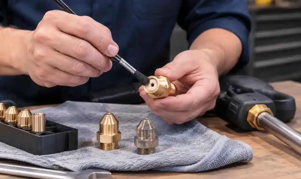 Spray nozzle wear inspection and maintenance for optimal coverage
FAQ
How do I calculate nozzle spacing for cooling systems?
Use the standard formula: Spacing = 2 × Height × tan(Angle/2) × 0.5 for 50% overlap. For cooling towers, verify droplet size and drift characteristics at your operating height—very fine sprays may require closer spacing due to evaporation losses before reaching the target.
What overlap percentage should I use for coating applications?
Coating applications typically require 60-70% overlap to achieve CV below 10%. This ensures uniform film thickness without streaking. Higher overlap increases nozzle count but is essential for quality finishes.
Can I use the same spacing calculation for all nozzle types?
No. The formula works for flat fan and cone patterns. Hollow cone nozzles require modified calculations accounting for the ring distribution. Air atomizing systems need empirical testing because pattern boundaries are indistinct and vary with air pressure.
How does pressure affect my coverage calculations?
Operating significantly off-rated pressure changes spray angle by 5-15%. This directly impacts coverage width and required spacing. Always verify your operating pressure matches nozzle specifications, or test actual spray angle at your pressure and recalculate spacing accordingly.
What is the maximum mounting height for uniform coverage?
Maximum practical height is approximately 1.5-2.0 meters for most industrial nozzles. Beyond this, droplet breakup, wind drift, and evaporation compromise coverage uniformity. If greater coverage width is needed, use wider spray angles rather than increasing height excessively.
How often should I verify coverage patterns?
Quarterly verification catches wear and drift before they cause quality problems. After any nozzle replacement, pressure changes, or mounting modifications, retest coverage immediately. Critical coating and chemical applications may justify monthly checks.
Conclusion
Optimizing spray coverage through proper pattern and spacing calculations reduces material waste, improves process consistency, and prevents costly coverage failures. The fundamental formula—Spacing = 2 × Height × tan(Angle/2) × Overlap Factor—provides the mathematical foundation, but successful implementation requires understanding how spray angle, mounting height, overlap percentage, and nozzle pattern types interact.
Industry standard 50% overlap delivers CV values of 10-15% suitable for most applications, while critical processes demand 60-70% overlap for CV below 10%. Mounting heights between 0.5-1.5 meters balance coverage width against droplet integrity. Always verify calculated spacing through collection pan testing or spray pattern analysis before finalizing system design.
The difference between adequate coverage and optimized coverage is systematic calculation, field verification, and ongoing maintenance. Facilities that implement proper spacing protocols report 20-30% reductions in chemical consumption and virtual elimination of rework from coverage defects. Whether designing new systems or troubleshooting existing installations, applying these calculation methods ensures uniform distribution and maximizes return on your spray system investment.