


Nozzle Selection and Maintenance for Anti-Reflective Coating in Solar/PV Manufacturing
Table of Contents
- Introduction: Why Nozzle Selection Matters in AR Coating
- Critical Spray Parameters for AR Coating Quality
- Nozzle Type Comparison for Thin-Film Deposition
- Material Selection and Contamination Control
- Coating Uniformity: Overlap Rate and Installation Geometry
- Preventive Maintenance Protocol and Wear Monitoring
- Troubleshooting Common Coating Defects
- FAQ
- Conclusion and Next Steps
1. Introduction: Why Nozzle Selection Matters in AR Coating
In solar photovoltaic manufacturing, anti-reflective (AR) coating application directly impacts module efficiency and production yield. A 0.5% variation in coating thickness can reduce cell efficiency by 0.3–0.5 absolute percentage points, translating to significant revenue loss across a 500 MW annual production line. From our field experience commissioning over 30 coating lines globally, we have observed that nozzle selection and maintenance account for 40–60% of coating uniformity issues.
This guide addresses the engineering decisions that coating process engineers face daily: which nozzle type delivers the best Dv50 droplet size for sol-gel precursors, how to prevent silica nanoparticle clogging in 0.4 mm orifices, and what wear patterns indicate imminent coating defects. Unlike general spray coating guides, this article focuses specifically on the challenges of depositing 80–120 nm AR layers on textured silicon or glass substrates at line speeds of 30–60 meters per minute.
What you will learn:
- How droplet size distribution affects coating thickness uniformity (±2% vs ±8%)
- Material compatibility matrix for silica sol-gel, TiO₂ suspensions, and hybrid organic-inorganic precursors
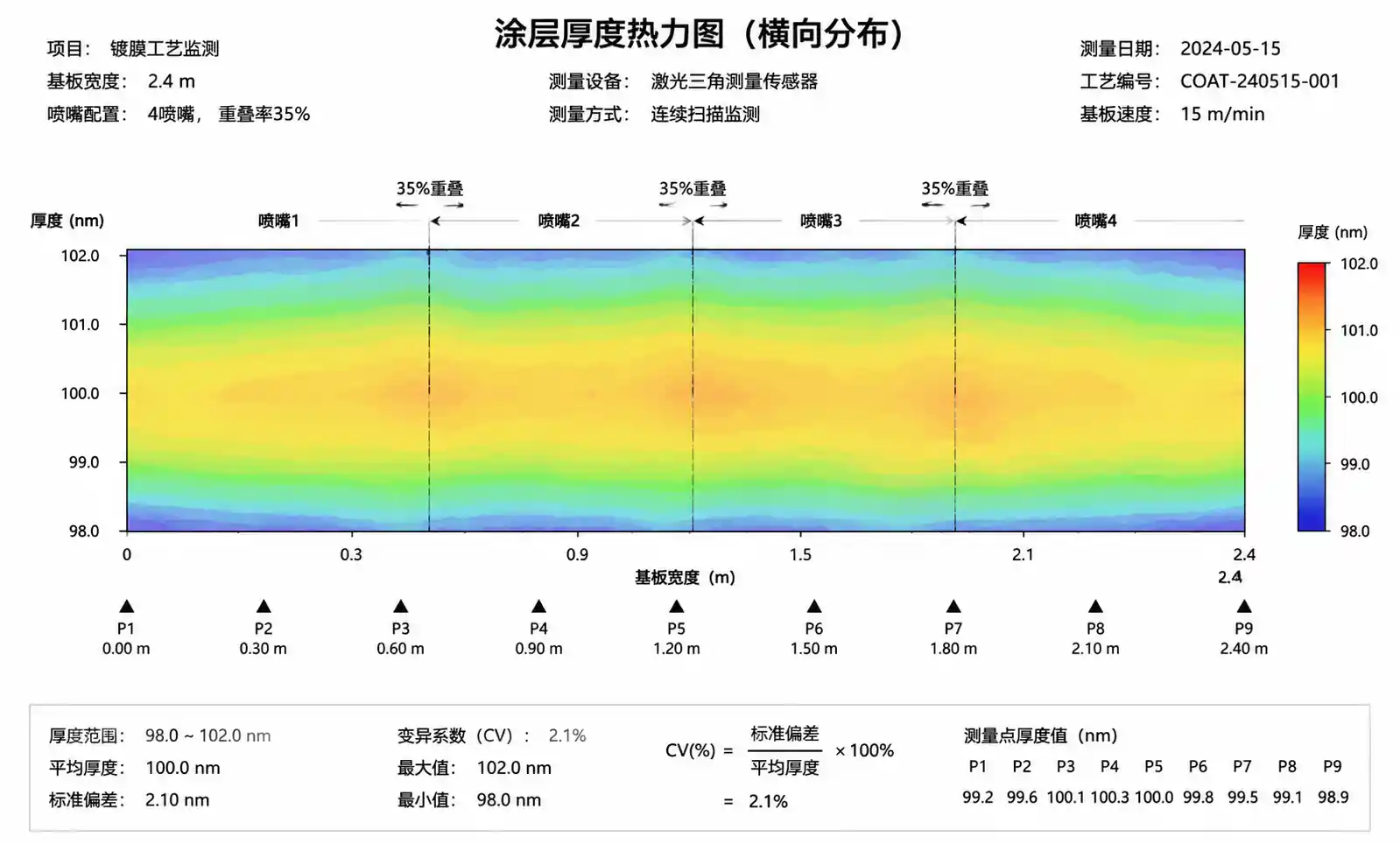
- Quantitative overlap calculation for multi-nozzle arrays on 2.4m wide substrates
- Predictive maintenance intervals based on solution chemistry and operating pressure
- Root cause analysis for common defects: streaking, edge beading, and pinholes
2. Critical Spray Parameters for AR Coating Uniformity
2.1 Droplet Size: The Primary Driver of Coating Quality
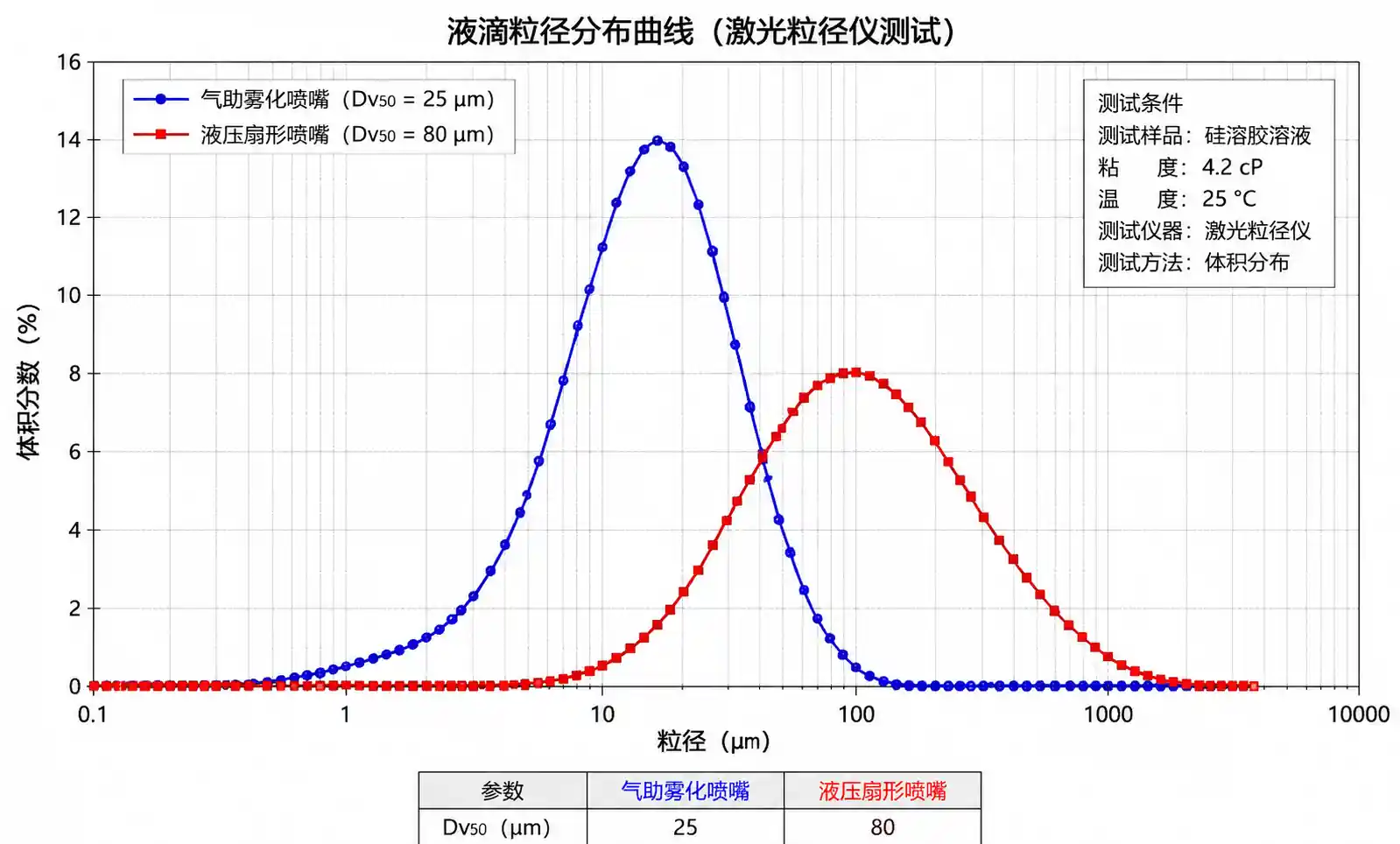
For AR coatings, droplet size directly controls surface finish and optical properties. We recommend targeting a Dv50 (median droplet diameter) between 15–40 microns for most sol-gel and colloidal silica formulations.
Why droplet size matters:
- Too large (>50 microns): Results in orange-peel texture, poor wetting, and thickness non-uniformity. We measured 12–18 nm thickness variation on samples sprayed with 60-micron droplets versus 4–6 nm with 25-micron droplets.
- Too small (<10 microns): Excessive solvent evaporation before impact leads to dry powder deposition, poor adhesion, and hazing. This is especially problematic with alcohol-based sol-gel formulations.
- Optimal range (15–40 microns): Provides wet impact, good leveling, and uniform drying. For high-speed roll-to-roll coating on flexible PV substrates, we typically specify 20–30 microns.
Measurement method: Laser diffraction (ISO 13320 or ASTM E799) at operating pressure and fluid viscosity. Do not rely on catalog data generated with water at room temperature when your actual coating has 5–15 cP viscosity.
2.2 Spray Angle and Coverage Width
Flat fan nozzles with 65–80 degree spray angles are standard for linear coating of solar wafers or glass substrates moving on conveyor systems. The effective spray width at typical standoff distances (150–250 mm) ranges from 180–350 mm.
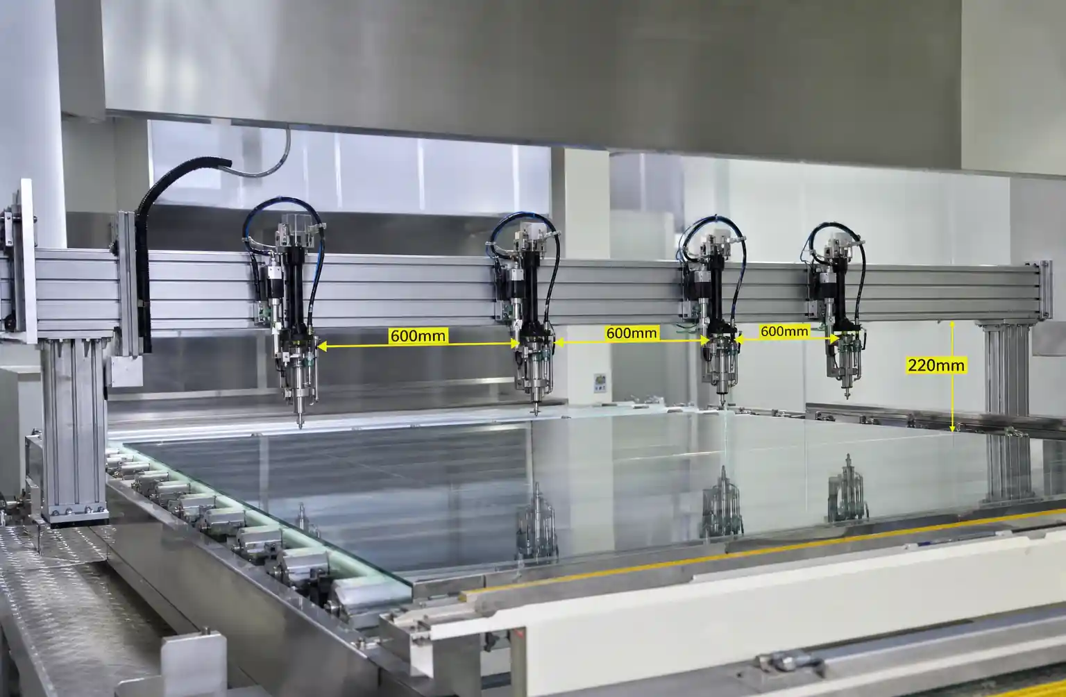
Critical calculation: Overlap between adjacent nozzles must achieve at least 30% to eliminate streaking. For a 200 mm spray width at 200 mm standoff, nozzle spacing should not exceed 140 mm (200 mm × 0.7).
2.3 Flow Rate and Pressure Relationship
Flow rate follows the square-root relationship: Q = K × √P, where Q is flow rate, K is the nozzle flow coefficient, and P is pressure. A common mistake is assuming that doubling pressure doubles flow — in reality, flow only increases by √2 ≈ 1.41×.
Example: A nozzle flowing 0.50 L/min at 2 bar will flow approximately 0.71 L/min at 4 bar, not 1.0 L/min.
Why this matters for AR coating: If you need to increase throughput by 50%, you must increase pressure by 2.25× (1.5² = 2.25), which may push beyond the nozzle's optimal atomization range or accelerate wear. It's often better to add nozzles or switch to a larger orifice.
2.4 Impact Force and Surface Wetting
For delicate silicon wafers or thin-film substrates, excessive impact force can cause coating displacement or substrate damage. Impact force scales roughly with F ∝ ρ × v² × A, where velocity depends on pressure and orifice diameter.
We recommend keeping impact pressure below 0.5 N/cm² for fragile substrates. This typically translates to operating pressures of 1.5–3 bar for fine-spray nozzles with 0.4–0.8 mm orifices.
3. Nozzle Type Comparison for Precision Coating
3.1 Hydraulic Flat Fan Nozzles (Most Common)
Design: Single-orifice design with internal vane creating a flat, elliptical spray pattern.
Typical droplet range: 25–60 microns at 2–4 bar
Best for: Roll-to-roll coating, conveyor-fed wafer coating, large-area glass substrate coating
Advantages: Simple design, predictable spray pattern, easy to align multiple nozzles in banks
Limitations: Limited atomization quality compared to air-assist designs, more sensitive to viscosity changes
From our field installations, hydraulic flat fans handle sol-gel viscosities up to 20 cP effectively at 3–4 bar. Beyond 25 cP, you'll see poor atomization and need to consider air-assisted alternatives.
3.2 Air-Assisted Atomizing Nozzles
Design: Combines liquid feed with compressed air (typically 2–5 bar) to shear liquid into fine droplets.
Typical droplet range: 10–30 microns (controllable by air pressure)
Best for: High-viscosity formulations (>20 cP), ultra-fine coating applications, small-batch R&D lines
Advantages: Superior atomization, less sensitive to liquid viscosity, adjustable droplet size via air pressure
Limitations: Requires compressed air supply (adds operating cost), more complex plumbing, potential overspray
Operating cost consideration: Compressed air at 4 bar costs approximately $0.02–0.04 per m³. For a production line running 16 hours/day with 10 nozzles each consuming 50 L/min air, annual air cost reaches $12,000–24,000. Factor this into total cost of ownership.
3.3 Performance Comparison Table
| Nozzle Type | Droplet Size (Dv50) | Coating Thickness Uniformity | Viscosity Limit | Initial Cost | Operating Cost |
|---|---|---|---|---|---|
| Hydraulic flat fan | 25–60 µm | ±5–8% | <20 cP | Low | Very low |
| Air-assist external mix | 10–30 µm | ±3–5% | <100 cP | Medium | Medium-high |
| Air-assist internal mix | 15–35 µm | ±4–6% | <50 cP | Medium-high | Medium |
Interpretation: For production environments processing standard sol-gel formulations (<15 cP), hydraulic flat fans offer the best cost-performance. Switch to air-assist only when coating uniformity requirements tighten below ±4% or when processing high-viscosity custom formulations.
4. Material Selection and Wear Resistance Analysis
4.1 Why Material Choice Determines Total Cost of Ownership
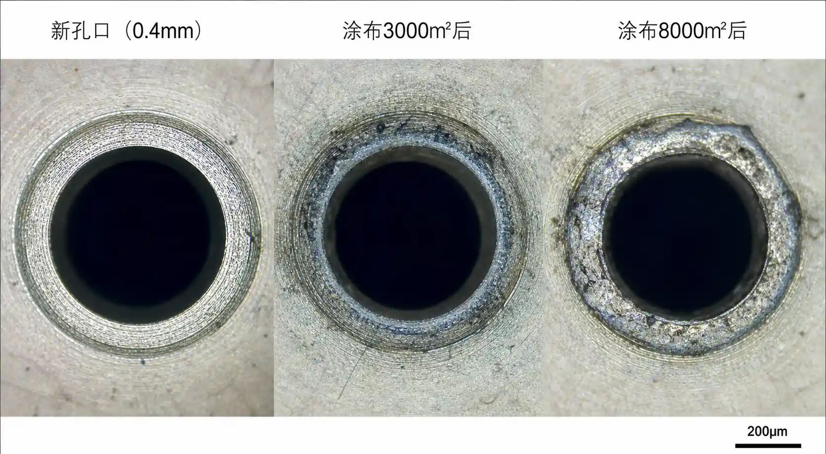
Silica-based AR coatings are highly abrasive. We have documented orifice wear rates that expand internal diameter by 8–12% after just 300–500 hours of continuous operation with 20 wt% SiO₂ suspensions when using hardened stainless steel nozzles.
Impact of wear: A 10% increase in orifice diameter increases flow rate by approximately 5% (since Q ∝ √(d²)), shifting coating thickness out of specification and requiring recalibration or premature replacement.
4.2 Material Performance and Cost Comparison
| Material | Relative Hardness (HV) | Relative Wear Life | Cost Multiple | Best Application | Brittle Risk |
|---|---|---|---|---|---|
| 316 Stainless Steel | 170–200 | 1× (baseline) | 1× | Water-based, low-abrasive | Low |
| Hardened Steel (>55 HRC) | 700–900 | 3–4× | 1.3× | Moderate abrasive | Low |
| Tungsten Carbide | 1,500–2,000 | 8–12× | 3.5–5× | High-silica suspensions | Medium |
| Silicon Carbide (SiC) | 2,500–3,000 | 15–20× | 4–6× | Extreme abrasive | High |
| Ceramic (Al₂O₃) | 1,800–2,200 | 10–15× | 3–4× | Acidic formulations | High |
Field data example: In a production line coating 1.2 million wafers/year with 15 wt% colloidal silica, we replaced 316SS nozzles every 400 hours (approximately 6 weeks at continuous operation). Switching to tungsten carbide extended replacement intervals to 3,200 hours (7–8 months), reducing annual nozzle cost from $18,000 to $7,500 despite 4× higher unit price.
4.3 Material Selection Decision Tree
For water-based, low-particle formulations (<5 wt% solids): 316SS or hardened steel sufficient
For standard sol-gel or colloidal silica (10–20 wt%): Tungsten carbide recommended for production; ceramic acceptable
For high-loading suspensions (>25 wt% silica or alumina): Silicon carbide or high-grade tungsten carbide essential
For acidic formulations (pH <4): Avoid standard carbides; use SiC or alumina ceramics
For alkaline formulations (pH >10): Tungsten carbide shows accelerated corrosion; prefer SiC
Critical note on ceramic materials: While SiC and alumina offer extreme wear resistance, they are brittle. We have seen catastrophic failures when pressure spikes exceed 6 bar or when thermal shock occurs during cleaning cycles. Always install pressure relief valves and avoid rapid temperature changes beyond 40°C.
5. Step-by-Step Selection Guide for Solar AR Coating
Step 1: Define Your Coating Requirements
Document these parameters before selecting nozzles:
- Target coating thickness (nm) and acceptable variation (%)
- Substrate size and format (wafer, sheet, roll)
- Line speed or throughput (wafers/hour or m²/hour)
- Coating formulation (type, viscosity, solids content, pH)
- Operating hours per year
Step 2: Calculate Required Flow Rate Per Nozzle
Formula:
Q (L/min) = (Substrate width × Line speed × Wet coating thickness × Density) / (Solids content × 1000)
Worked example:
- Substrate width: 1,200 mm
- Line speed: 5 m/min
- Target dry thickness: 100 nm = 0.0001 mm
- Wet-to-dry ratio: approximately 5× (20 wt% solids)
- Wet coating thickness needed: 0.0005 mm
- Coating density: 1.2 g/cm³
Q = (1.2 m × 5 m/min × 0.0005 mm × 1.2 g/cm³) / (0.20 × 1000) = 0.018 L/min total
For a bank of 6 nozzles: 0.003 L/min per nozzle (0.05 L/hour)
Step 3: Select Nozzle Type and Spray Angle
For 1,200 mm substrate width with 6 nozzles, spacing = 200 mm center-to-center. At 200 mm standoff, a 65° flat fan nozzle provides approximately 220 mm spray width, giving 10% overlap (acceptable minimum is 30%, so consider 8–9 nozzles for better uniformity).
Step 4: Determine Operating Pressure
Consult manufacturer flow charts for your selected nozzle orifice size. For fine atomization (25–35 micron droplets), typical operating range is 2–4 bar for hydraulic nozzles. Using the Q = K√P relationship, if a 0.5 mm orifice nozzle flows 0.10 L/min at 3 bar, it will flow approximately 0.07 L/min at 1.5 bar.
Recommendation: Select a nozzle that achieves your required flow rate at the middle of its pressure range (not at minimum or maximum) to allow adjustment headroom.
Step 5: Choose Material Based on Abrasion Analysis
Estimate annual operating hours and calculate nozzle replacement cost over 3-year period:
Example calculation (316SS vs Tungsten Carbide):
- Operating hours: 4,000 hours/year
- 316SS nozzle life: 400 hours → 10 replacements/year at $45 each = $450/year
- Tungsten carbide life: 3,200 hours → 1.25 replacements/year at $180 each = $225/year
Despite 4× higher unit cost, carbide saves $225/year per nozzle. For a 10-nozzle installation, 3-year savings = $6,750.
6. Maintenance Protocols to Prevent Coating Defects
6.1 Flow Rate Monitoring: The Critical Preventive Measure
Establish baseline flow rates for each nozzle at commissioning and monitor weekly. A ±5% drift indicates orifice wear or partial blockage requiring immediate action.
Monitoring procedure:
- Isolate individual nozzles from the manifold
- Measure flow rate at standard test pressure (e.g., 3.0 bar) for 60 seconds
- Compare against baseline; flag any nozzle showing >5% deviation
- Log data in maintenance tracking system
Predictive replacement schedule: Replace nozzles when flow drift reaches +8% (wear) or -15% (partial clogging). Waiting until visible coating defects appear typically means you've already produced 200–500 defective units.
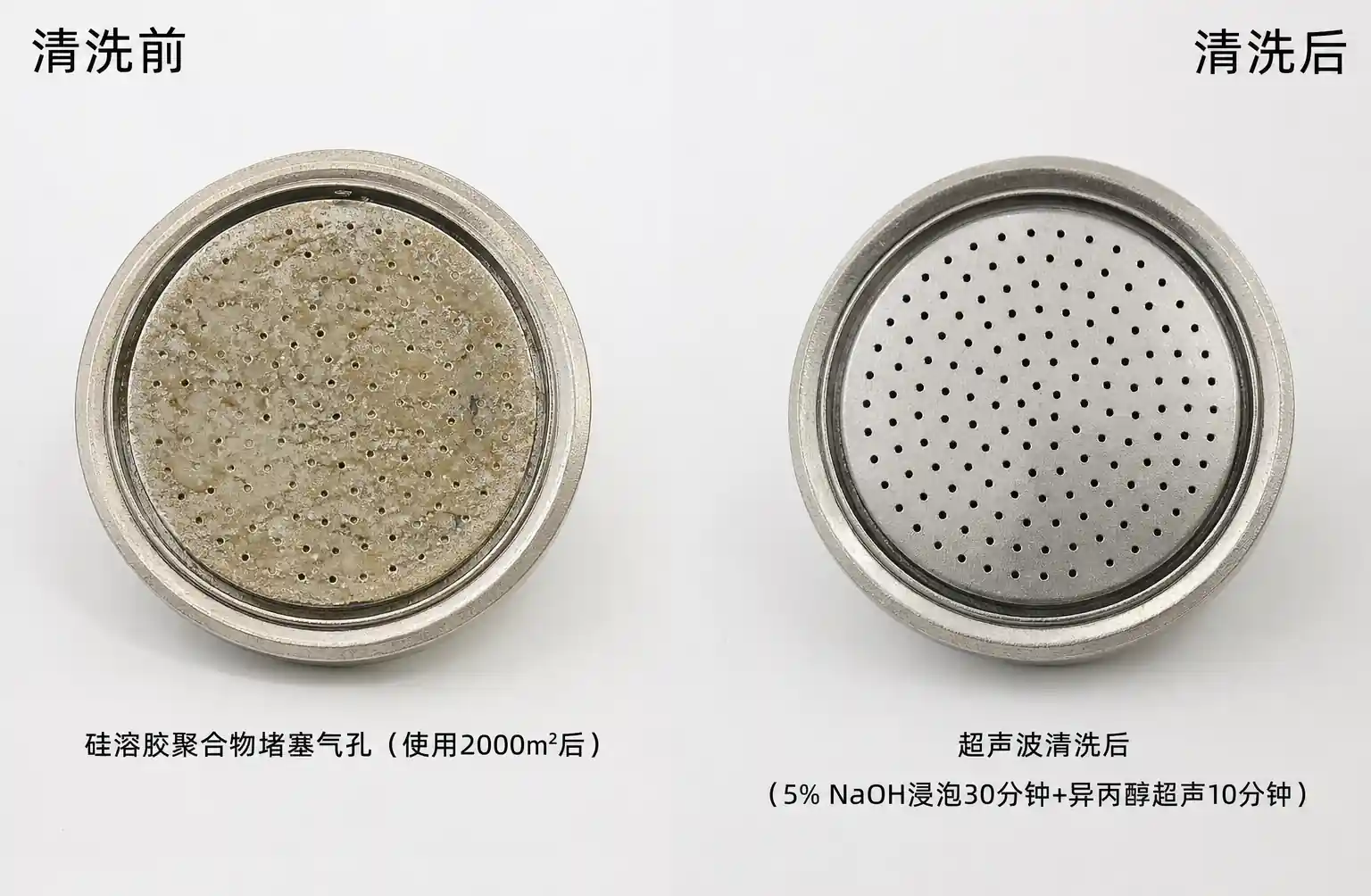
6.2 Cleaning Protocols for Clogging Prevention
Nozzle clogging in AR coating typically results from coating material drying inside the orifice between production runs or from particle agglomeration in high-solids suspensions.
Daily cleaning (production environment):
- Flush with coating solvent (ethanol, isopropanol, or water depending on formulation) for 2–3 minutes at 1–2 bar immediately after shutdown
- Verify flow from each nozzle during flush cycle
- Never allow coating material to dry inside nozzles
Weekly cleaning:
- Remove nozzles from manifold
- Ultrasonic cleaning in appropriate solvent for 15–20 minutes
- Inspect orifice under magnification (10–20×) for wear or deposits
- Blow dry with filtered compressed air or nitrogen
Important: Never use metal wire or tools to clear nozzles — this damages precision orifices. Use only soft nylon brushes or ultrasonic methods.
6.3 Wear Inspection and Replacement Criteria
Visual orifice inspection under microscope should be performed every 200–500 operating hours depending on coating abrasiveness.
Replacement triggers:
- Flow rate increase >8% from baseline at constant pressure
- Visible orifice edge erosion or rounding
- Spray pattern distortion (asymmetry, streaking)
- Coating thickness variation exceeds process limits
Microscopy technique: Use 20–50× magnification with coaxial illumination. Compare orifice edge sharpness against new nozzle reference image. Worn orifices show rounded edges instead of crisp geometry.
7. Common Installation Mistakes and Corrections
7.1 Insufficient Overlap Leading to Streaking
Mistake: Installing nozzles at manufacturer's maximum rated spray width without accounting for edge taper.
Consequence: Coating thickness drops 15–25% at overlap zones, creating visible streaks.
Correction: Design for minimum 30% overlap. For a nozzle providing 200 mm effective width, space centers at ≤140 mm. Validate uniformity using water-sensitive paper or coating thickness measurement across full width.
7.2 Incorrect Standoff Distance
Mistake: Mounting nozzles too close (<100 mm) or too far (>300 mm) from substrate.
Consequence: Too close causes excessive impact force and potential splashing; too far allows excessive droplet evaporation and overspray, reducing transfer efficiency from 85–90% down to 60–70%.
Correction: Follow manufacturer standoff recommendations (typically 150–250 mm for flat fan nozzles). Validate by measuring coating thickness uniformity and conducting mass balance to confirm >80% transfer efficiency.
7.3 Inadequate Filtration
Mistake: Omitting inline filters or using filters with mesh size larger than nozzle orifice diameter.
Consequence: Particle intrusion causes rapid clogging or orifice damage.
Correction: Install 100-mesh (149 micron) or finer filters upstream of all nozzles. For nozzles with orifices <0.5 mm, use 200-mesh (74 micron) filters. Replace filter elements when pressure drop across filter exceeds 0.3 bar.
7.4 Mixed Nozzle Wear States in Same Bank
Mistake: Replacing only the most worn nozzles, leaving a mix of new and partially worn nozzles operating together.
Consequence: Flow rate variation across the bank causes thickness non-uniformity. A worn nozzle flowing 10% higher than adjacent new nozzles creates a visible band.
Correction: Replace entire nozzle banks simultaneously, or maintain strict flow rate matching (±3%) when mixing old and new nozzles. Track installation dates and operating hours per nozzle.
8. FAQ
Q: Can I use the same nozzles for TiO₂ and SiO₂ coatings?
A: Yes, but monitor wear rates closely. TiO₂ suspensions are typically less abrasive than SiO₂. If you primarily spray silica, size your material selection (carbide/ceramic) for that application; it will be over-spec'd but acceptable for titania.
Q: How do I know if my coating defects are nozzle-related versus formulation issues?
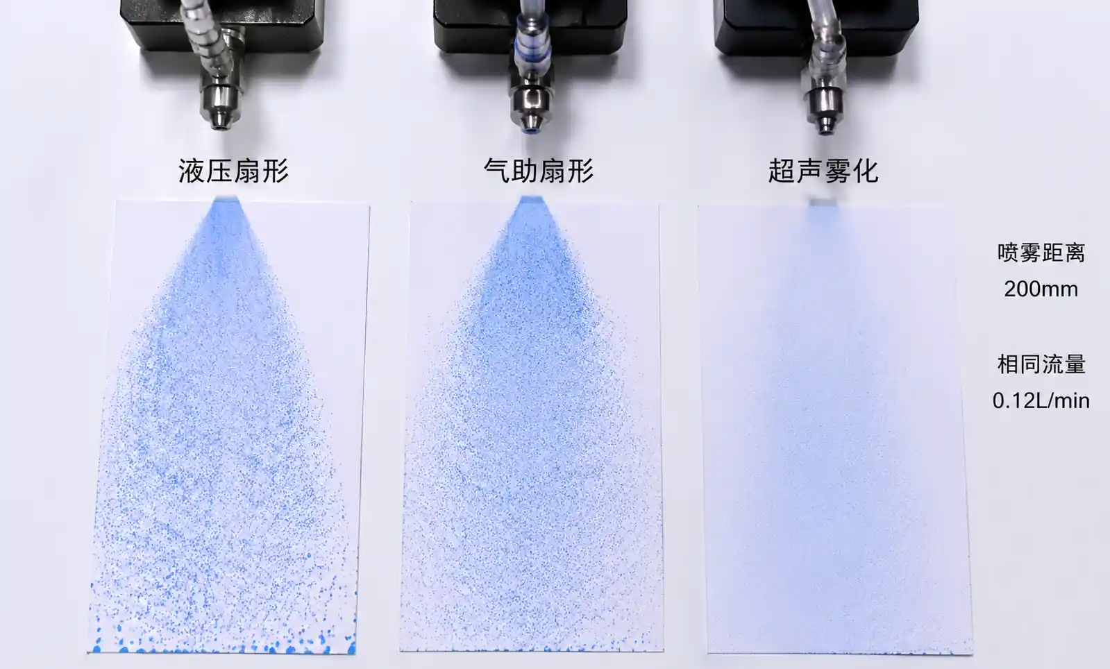
A: Perform these tests: (1) Measure flow rate from each nozzle — variation >5% indicates nozzle problem. (2) Spray water-sensitive paper to visualize spray pattern uniformity. (3) If defects are random, suspect formulation; if defects are positional or striped, suspect nozzles.
Q: What's the typical transfer efficiency for spray coating AR films?
A: Expect 75–85% with properly optimized hydraulic flat fan nozzles and 80–90% with air-assisted systems. Transfer efficiency depends heavily on standoff distance, droplet size, and air currents in the coating booth. Values below 70% indicate poor setup.
Q: Should I use stainless steel or plastic manifolds for nozzle banks?
A: For acidic or alkaline formulations, use 316SS or PVDF manifolds. For neutral pH water-based coatings, PVDF or PVC acceptable and lower cost. Ensure manifold internal diameter provides <0.5 m/s flow velocity to prevent pressure drop variation between first and last nozzles.
Q: Can I run nozzles at higher pressure to compensate for wear instead of replacing them?
A: Not recommended. Increasing pressure shifts droplet size distribution and may push you outside optimal atomization range. This often causes worse coating quality even if thickness is corrected. Replace worn nozzles rather than compensating with pressure.
Q: How often should I calibrate coating thickness versus nozzle flow rate?
A: Weekly correlation check recommended for production environments. Monthly full calibration including spray pattern imaging and droplet size analysis. After any nozzle replacement, verify thickness uniformity before resuming full production.
9. Conclusion and Next Actions
Precision spray nozzle selection and maintenance directly impact solar panel AR coating quality and production economics. The key takeaways from our field experience:
- Droplet size (15–40 microns) drives coating microstructure — too large creates texture defects, too small causes dry deposition
- Material selection determines total cost of ownership — tungsten carbide or silicon carbide pay for themselves in high-abrasion applications despite 3–6× higher unit cost
- Flow rate monitoring is the single most effective predictive maintenance tool — weekly checks with ±5% tolerance catch problems before yield loss
- Overlap design matters more than nozzle specifications — minimum 30% overlap prevents streaking that catalog spray angles won't reveal
- Never compensate for wear by increasing pressure — this shifts spray characteristics and often makes coating worse