


Large Flow Nozzles for Marine Scrubbers: What to Consider
Table of Contents
- Introduction: Why Nozzle Selection Matters in Marine Scrubbers
- Critical Performance Parameters for Scrubber Nozzles
- Nozzle Type Comparison for Marine Scrubber Applications
- Material Selection: Surviving Seawater and Acidic Conditions
- Flow Rate and Pressure Relationship in Large Flow Systems
- Installation Configuration and Common Mistakes
- Maintenance Strategy and Total Cost of Ownership
- FAQ
- Conclusion
1. Introduction: Why Nozzle Selection Matters in Marine Scrubbers
Marine scrubbers—specifically Exhaust Gas Cleaning Systems (EGCS)—have become essential equipment for vessels operating under IMO 2020 sulfur cap regulations. These systems remove sulfur oxides (SOx) and particulate matter from exhaust gases by spraying seawater or freshwater with alkaline additives into the gas stream. The nozzles in these scrubbers must deliver high flow rates, uniform coverage, and fine atomization while withstanding corrosive conditions and operating continuously for thousands of hours between port calls.
From our field experience supporting marine scrubber installations across container ships, bulk carriers, and cruise vessels, we have seen that nozzle selection directly impacts scrubber efficiency, pressure drop, and operational cost. A poorly selected nozzle can result in insufficient SO₂ removal, excessive pump energy consumption, premature wear requiring unscheduled maintenance, and potential non-compliance with emission regulations during port state control inspections.
This guide focuses on large flow nozzles—typically those delivering 50 to 500 gallons per minute (190–1900 liters per minute) per nozzle at pressures ranging from 20 to 80 PSI (1.4–5.5 bar). We will cover the engineering parameters that matter most, compare nozzle types used in scrubber towers, explain material choices for seawater duty, and provide practical selection criteria based on actual installations.
2. Critical Performance Parameters for Scrubber Nozzles
2.1 Flow Rate and Scrubber Liquid-to-Gas Ratio
Marine scrubbers operate at a liquid-to-gas ratio (L/G) typically between 5 and 20 liters of water per cubic meter of exhaust gas, depending on exhaust sulfur content and required removal efficiency. For a 15 MW main engine producing approximately 70,000 m³/h of exhaust gas at full load, a scrubber with L/G = 10 requires 700,000 liters/hour (185 GPM per nozzle if using 16 nozzles, or 3,083 liters/min total).
The flow rate through each nozzle follows the standard hydraulic relationship:
Q = Cv × √ΔP
Where:
- Q = flow rate (GPM or L/min)
- Cv = flow coefficient (nozzle-specific constant)
- ΔP = pressure drop across the nozzle (PSI or bar)
A common mistake is assuming that increasing pressure from 40 PSI to 80 PSI will double the flow rate. In reality, flow increases by only √2 ≈ 1.41×. To double flow, you must quadruple the pressure or use a nozzle with a larger orifice.
2.2 Droplet Size Distribution
Effective SO₂ absorption requires maximizing liquid surface area, which means smaller droplets are better—but not too small. We typically recommend droplets in the 200–800 micron (Dv50) range for marine scrubbers:
- Below 200 microns: Droplets may be entrained in the exhaust gas flow and carried out of the scrubber, causing excessive water carryover and mist eliminator loading.
- 200–500 microns: Optimal for high absorption efficiency; provides large surface area while maintaining acceptable settling velocity.
- 500–800 microns: Acceptable for open-loop seawater scrubbers where contact time is longer; reduces pump pressure requirements.
- Above 800 microns: Insufficient surface area; requires excessive water flow to achieve target SO₂ removal.
Droplet size is primarily controlled by nozzle orifice diameter and spray pressure. Higher pressures produce finer atomization, but also increase pump energy consumption significantly (pump power scales with pressure).
2.3 Spray Angle and Coverage Uniformity
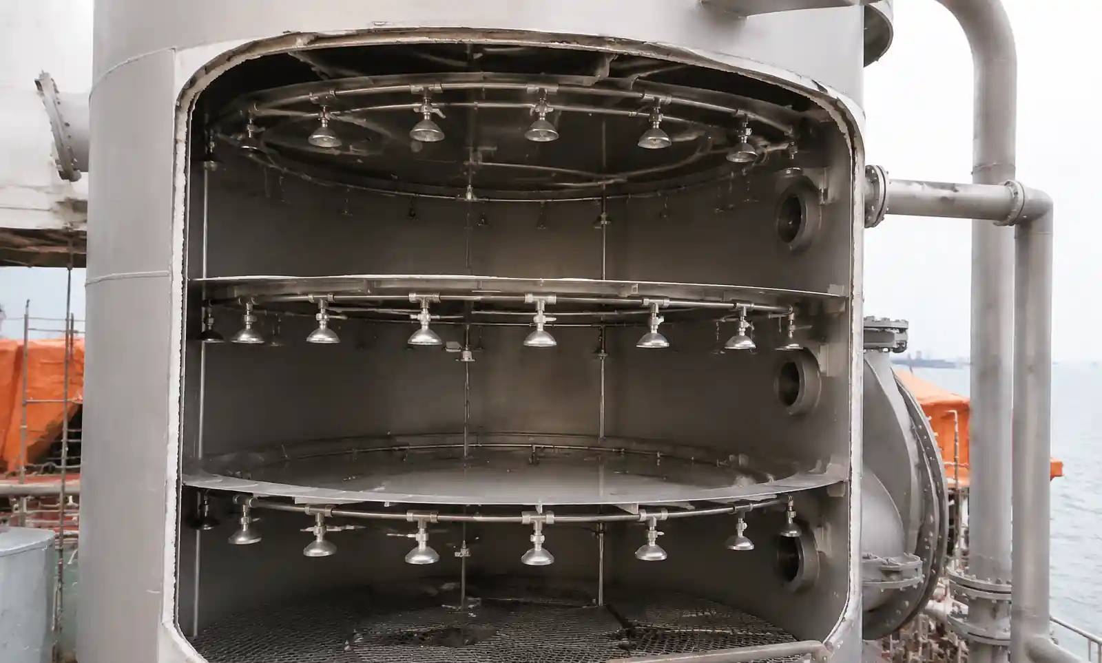
Scrubber towers typically have diameters from 1.5 to 4 meters. Achieving complete cross-sectional coverage without dead zones requires careful selection of spray angle and nozzle spacing. Most marine scrubber installations use one of these configurations:
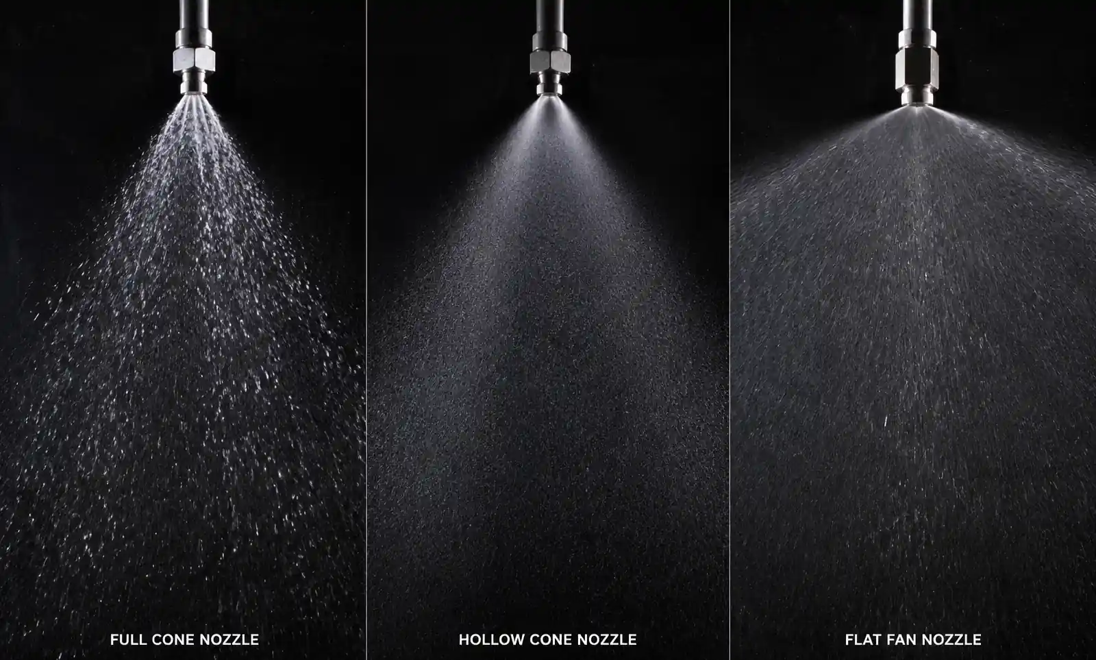
- Full cone nozzles with 60–90° spray angles: Provide solid coverage with overlapping spray patterns; typically require 12–24 nozzles per spray level.
- Wide-angle full cone (90–120°): Fewer nozzles needed but may have weak spray density at the edges.
- Hollow cone nozzles: Concentrate spray at the cone periphery; useful for specific gas distribution patterns but less common in modern scrubbers.
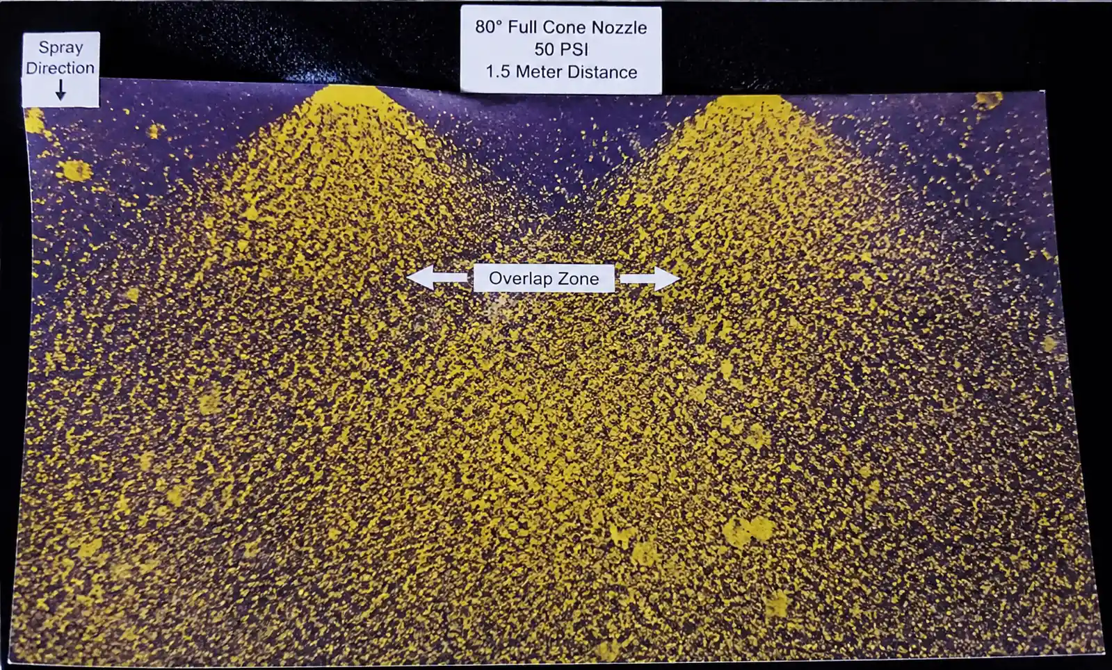
A critical parameter is the overlap ratio, defined as the ratio between the spray coverage diameter at a given distance and the nozzle spacing. We recommend an overlap ratio of 1.5:1 minimum to ensure no dry spots. Inadequate overlap leads to channeling—exhaust gas bypassing the spray zone and exiting with insufficient treatment.
2.4 Pressure Drop and Pump Energy Consideration
Since scrubber pumps run continuously at sea, energy consumption is a major operational cost. Pump power is given by:
P = (Q × ΔP) / (3960 × η)
Where:
- P = pump power (HP)
- Q = flow rate (GPM)
- ΔP = total pressure including nozzle pressure drop (PSI)
- η = pump efficiency (typically 0.70–0.85)
For a scrubber system flowing 3,000 GPM at 60 PSI with 75% pump efficiency:
P = (3000 × 60) / (3960 × 0.75) = 60.6 HP ≈ 45 kW
Operating 8,000 hours per year at $0.10/kWh, this costs $36,000 annually in electricity. Reducing nozzle pressure drop by 20 PSI saves approximately $12,000/year—enough to justify a premium nozzle selection.
3. Nozzle Type Comparison for Marine Scrubber Applications
| Nozzle Type | Spray Pattern | Typical Flow per Nozzle (GPM @ 40 PSI) | Droplet Size (Dv50) | Clogging Resistance | Best Application |
|---|---|---|---|---|---|
| Hydraulic Full Cone | Solid filled cone, 60–90° | 80–250 | 300–600 microns | Moderate (1.5–3mm orifice) | Open-loop seawater scrubbers, standard SO₂ removal |
| Spiral Full Cone | Uniform filled cone via helical flow | 60–200 | 250–500 microns | Good (tangential inlet reduces particle buildup) | Closed-loop with suspended solids present |
| Hollow Cone | Ring-shaped spray, liquid at periphery | 50–180 | 200–450 microns | Moderate to Poor | Specific gas distribution requirements, less common |
| Air-Assisted Atomizing | Very fine mist via compressed air | 20–120 | 50–200 microns | Poor (small passages) | High-efficiency hybrid scrubbers, shore power available |
| Wide-Angle Full Cone | Flat trajectory, 90–120° | 100–300 | 400–700 microns | Good (large orifice) | Large diameter towers, reduced nozzle count |
3.1 Why Hydraulic Full Cone Dominates Marine Scrubbers
Approximately 75% of marine scrubber installations use hydraulic full cone nozzles because they offer the best balance of:
- Simplicity: Single-fluid operation (no compressed air required)
- Reliability: Fewer internal components to clog or corrode
- Flow capacity: Large orifices (typically 6–12mm) handle high flow rates
- Pressure range: Effective from 20–80 PSI, matching typical scrubber pump capabilities
In our experience, spiral full cone nozzles offer superior performance when the scrubber water contains suspended calcium carbonate or magnesium hydroxide (common in closed-loop systems). The tangential inlet design creates a self-cleaning swirl that resists orifice buildup better than straight-through full cone designs.
3.2 When to Consider Air-Assisted Nozzles
Air-assisted atomizing nozzles produce much finer droplets (50–200 microns) and can achieve SO₂ removal efficiencies 10–15% higher than hydraulic nozzles at the same water flow rate. However, they require compressed air at 40–80 PSI, adding complexity and energy consumption. We recommend air-assisted nozzles only for:
- Hybrid scrubbers with very high sulfur content exhaust (>3.5% sulfur HFO)
- Space-constrained retrofits where tower height is limited
- Shore-based or platform installations where compressed air is readily available
For standard marine installations, the added maintenance burden and air compressor energy typically outweigh the efficiency gain.
4. Material Selection: Surviving Seawater and Acidic Conditions
Marine scrubber nozzles face two primary degradation mechanisms: corrosion from acidic, chloride-rich water, and erosion from particulate matter and high-velocity flow.
4.1 Material Options and Trade-offs
| Material | Relative Hardness (HRC) | Corrosion Resistance (Seawater + Acidic) | Erosion Life (Relative) | Cost Factor | Typical Service Life (Hours) | Best Use Case |
|---|---|---|---|---|---|---|
| 316 Stainless Steel | 15–20 | Good (but pitting in stagnant seawater) | 1× (baseline) | 1.0× | 8,000–12,000 | Short-term or trial installations |
| Duplex Stainless (2205) | 25–30 | Excellent (high chloride tolerance) | 2.5× | 2.5× | 20,000–30,000 | Open-loop seawater scrubbers (recommended) |
| Hastelloy C-276 | 20–25 | Exceptional (acidic + chloride) | 1.5× | 8.0× | 25,000+ | Closed-loop with acidic additives |
| Silicon Carbide Insert | 70–75 (Vickers) | Excellent (inert ceramic) | 10–15× | 4.0× | 50,000–80,000 | High-erosion conditions, abrasive particles |
| Tungsten Carbide Insert | 65–70 (Vickers) | Moderate (requires nickel binder protection) | 8–12× | 5.0× | 40,000–70,000 | Freshwater or low-chloride closed-loop |
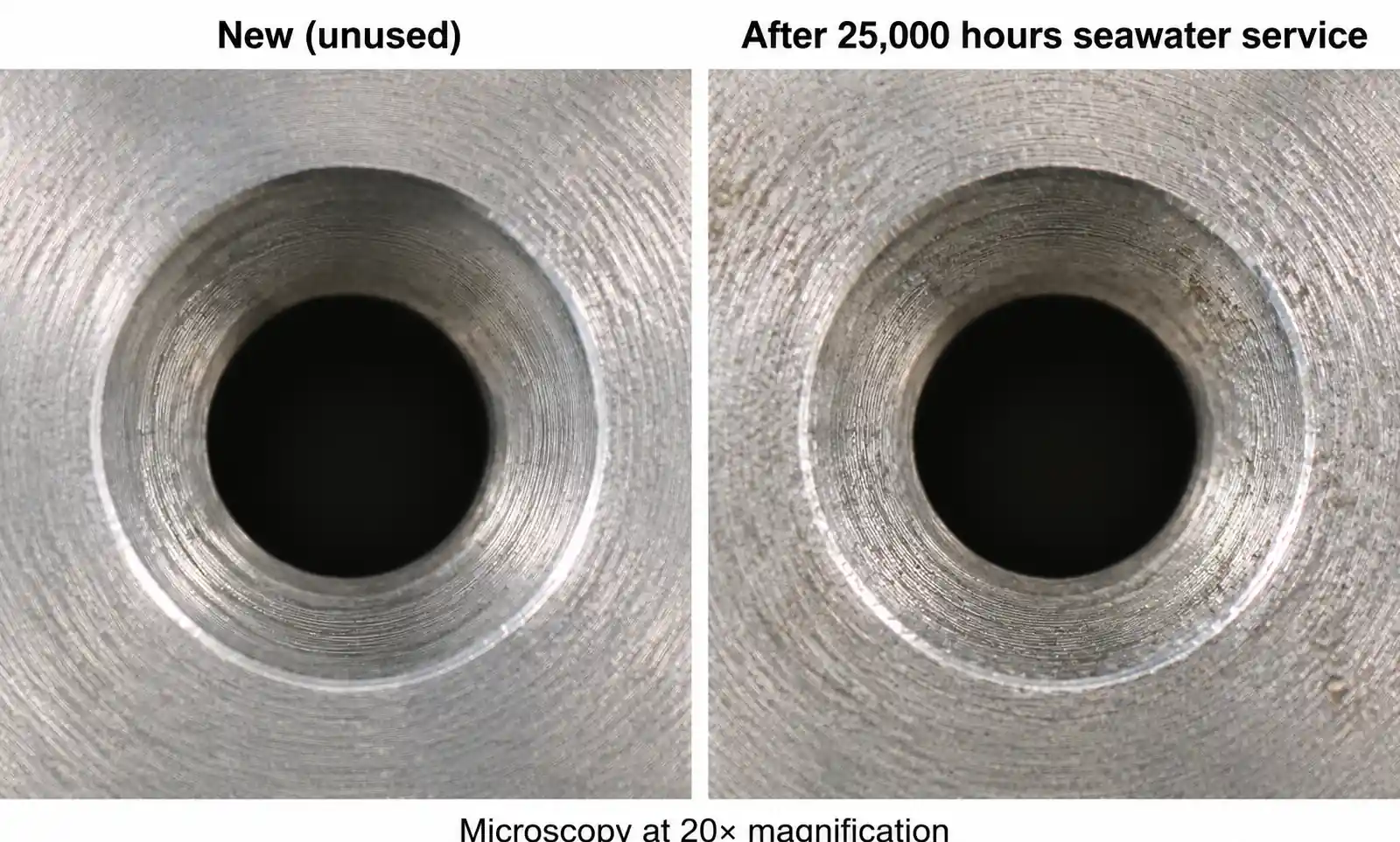
4.2 Field Experience: Duplex vs. 316 Stainless
In a comparative study we conducted on a 15 MW scrubber system aboard a container vessel, 316 stainless steel nozzles operating in open-loop seawater mode showed visible orifice erosion after 10,000 operating hours, with flow rates increasing by 12–18% (indicating loss of spray control). Duplex 2205 nozzles on the same system maintained flow rates within 5% of original specification after 25,000 hours.
The cost premium for duplex stainless is approximately 2.5×, but the extended service life more than compensates when you factor in:
- Reduced maintenance downtime: Nozzle replacement requires tower access, typically 8–12 hours of work per spray level
- Consistent scrubber performance: Worn nozzles with enlarged orifices deliver lower spray velocity and larger droplets, reducing SO₂ absorption efficiency
- Fewer spare parts: A duplex nozzle lasting 25,000 hours vs. 10,000 hours reduces spares inventory by 60%
We recommend duplex stainless steel (UNS S32205 or S32750) as the default choice for open-loop seawater scrubbers. Reserve silicon carbide or tungsten carbide inserts for situations where:
- Abrasive particles are present (e.g., closed-loop systems using limestone slurry)
- Extremely long service intervals are required (offshore platforms, remote vessels)
- High spray pressures (>80 PSI) accelerate erosion
4.3 Corrosion Failure Modes
From failure analysis of returned nozzles, the most common corrosion mechanisms are:
- Crevice corrosion at threaded connections (use anti-seize compound rated for seawater)
- Pitting corrosion on downstream side of orifice where velocity is highest
- Stress corrosion cracking in 316 SS when chloride concentration exceeds 1,000 ppm and temperature exceeds 50°C
Duplex stainless alloys resist all three mechanisms significantly better than 316 SS due to their balanced ferrite-austenite microstructure and higher chromium/molybdenum content.
5. Flow Rate and Pressure Relationship in Large Flow Systems
5.1 Calculating Required Nozzle Capacity
For a given scrubber system, the total water flow requirement is determined by the L/G ratio and exhaust gas volume. The number of nozzles needed depends on individual nozzle capacity at available pump pressure.
Worked Example: 18 MW Main Engine Scrubber
Given:
- Exhaust gas flow: 85,000 m³/h at engine MCR (maximum continuous rating)
- Target L/G ratio: 12 L/m³
- Available pump pressure: 50 PSI (3.45 bar)
- Scrubber tower diameter: 2.5 meters
- Target spray angle: 80° full cone
Step 1: Calculate total water flow requirement
Total flow = 85,000 m³/h × 12 L/m³ = 1,020,000 L/h = 17,000 L/min = 4,490 GPM
Step 2: Select nozzle model and determine individual flow rate
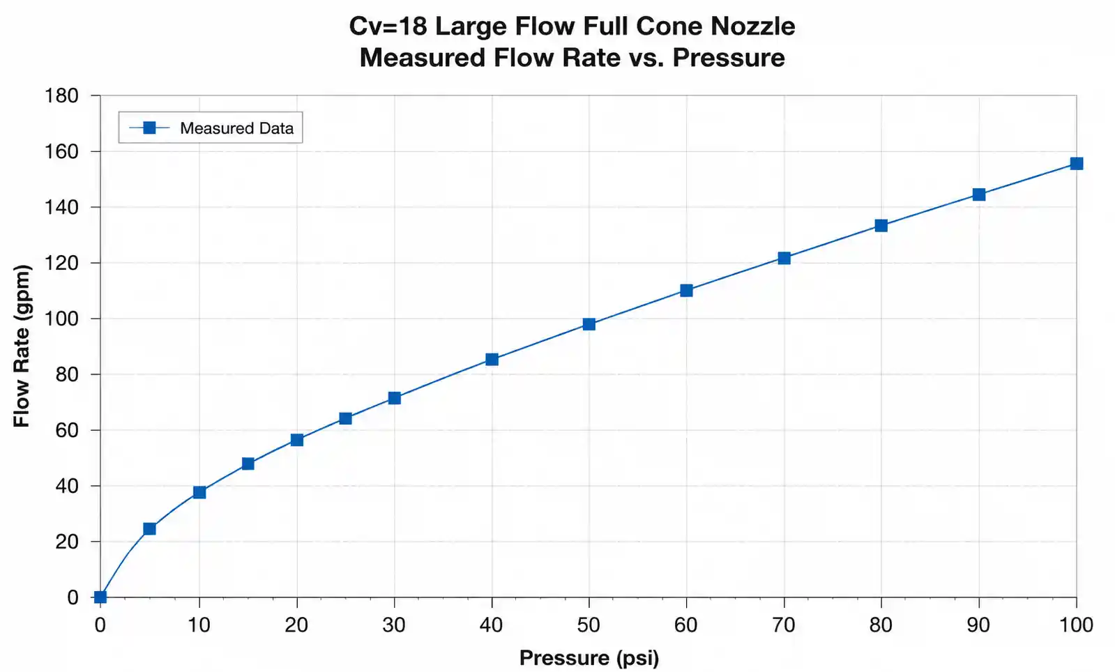
Using a large-flow full cone nozzle with Cv = 18 at 50 PSI:
Q = 18 × √50 = 18 × 7.07 = 127 GPM per nozzle
Step 3: Calculate number of nozzles required
Nozzles needed = 4,490 GPM / 127 GPM = 35.4 → round up to 36 nozzles
Step 4: Verify coverage with spray angle
At 80° spray angle, spray diameter at 1.5 meters below nozzle = 1.5 × tan(80°/2) × 2 = 2.0 meters
For a 2.5-meter diameter tower, arrange nozzles in three circular levels (12 nozzles per level) with 60° radial spacing. This configuration provides overlap ratio of approximately 1.6:1—adequate for uniform coverage.
5.2 Pressure Drop vs. Flow Rate Curve
Understanding the flow-pressure relationship allows you to predict system behavior during operation. For the nozzle above (Cv = 18):
| Pressure (PSI) | Flow Rate (GPM) | Pump Power Required (HP)* | Droplet Size Dv50 (microns) |
|---|---|---|---|
| 20 | 80 | 28 | 520 |
| 30 | 98 | 39 | 450 |
| 40 | 113 | 51 | 400 |
| 50 | 127 | 63 | 360 |
| 60 | 139 | 75 | 330 |
| 80 | 161 | 100 | 290 |
*Calculated for 36 nozzles total, 75% pump efficiency Approximate values; actual droplet size depends on nozzle internal geometry
This table reveals an important trade-off: increasing pressure from 40 to 80 PSI (2×) increases pump power by 96% but only reduces droplet size by 27.5%. For most scrubber applications, operating pressure of 40–50 PSI provides the best balance of atomization and energy efficiency.
5.3 Accounting for Nozzle Wear
As nozzles erode, the orifice diameter increases, which increases flow rate at constant pressure. For 316 stainless nozzles, we typically observe 10–15% flow increase after 10,000 hours in seawater service. This has two consequences:
- Total system flow increases, which can overload the pump or recirculation system
- Spray velocity decreases (since the orifice is larger), resulting in larger droplets and reduced absorption efficiency
To maintain consistent scrubber performance, we recommend flow testing nozzles annually and replacing any that exceed 110% of nameplate flow rate.
6. Installation Configuration and Common Mistakes
6.1 Spray Level Arrangement
Most marine scrubbers use 2–4 spray levels arranged vertically within the tower. Each level consists of multiple nozzles (typically 8–24 per level) arranged in a circular pattern or radial arms. Key design rules:
- Vertical spacing: 1.5–3.0 meters between spray levels to allow droplet development and gas-liquid contact
- Radial offset: Rotate each level 15–30° relative to the level above to eliminate vertical dead zones
- Downward spray angle: 10–15° below horizontal to maximize residence time and prevent upward mist carryover
6.2 Common Installation Mistakes We've Seen
Mistake #1: Inadequate spray overlap Installing too few nozzles or using too narrow a spray angle creates untreated gas channels. We investigated one scrubber failing emission compliance and found that 30% of the tower cross-section had no spray coverage. Adding four nozzles per level (20% increase) brought the system into compliance.
Mistake #2: Orienting nozzles too far downward Some installers point nozzles at 30–45° downward, thinking this maximizes contact time. In reality, this concentrates spray in the lower tower section and creates a dry zone in the upper section where hot exhaust gas first enters. We recommend 10–15° maximum downward angle, with most nozzles at or slightly above horizontal.
Mistake #3: Using brass or carbon steel pipe nipples Even when the nozzle body is corrosion-resistant duplex stainless, connecting it with a brass or carbon steel nipple creates a galvanic cell that accelerates corrosion. Always use the same material for nozzle, nipple, and mounting bracket. We've seen brass nipples fail after only 2,000 hours in seawater service.
Mistake #4: Over-tightening threaded nozzles Ceramic insert nozzles (silicon carbide or tungsten carbide) are brittle. Over-torquing the threaded connection can crack the ceramic insert. Follow manufacturer torque specifications (typically 25–40 ft-lbs for 1" NPT connections) and use a torque wrench.
6.3 Access and Serviceability
Plan for nozzle maintenance during the design phase. Requirements:
- Manway access: Minimum 600mm diameter access door on each spray level
- Spray pipe drain valves: Allow complete drainage before opening the tower for maintenance
- Nozzle removal clearance: Ensure sufficient space to unthread nozzles without dismantling spray pipes
- Spare nozzle storage: Keep 25% spares onboard (e.g., 9 spares for a 36-nozzle system)
7. Maintenance Strategy and Total Cost of Ownership
7.1 Flow Testing and Performance Monitoring
The most effective preventive maintenance strategy is periodic flow testing. We recommend:
- Baseline flow test at commissioning (measure actual flow rate at specified pressure)
- Annual flow test during planned maintenance or drydock
- Replace nozzles when flow exceeds 110% of baseline or spray pattern shows obvious asymmetry
Flow testing requires temporarily installing a flow meter in the spray pipe feeding a single nozzle. Test at the normal operating pressure (typically 40–50 PSI) and compare against the manufacturer's flow curve. A flow increase of 10–15% indicates orifice erosion; replace the nozzle before performance degrades further.
7.2 Total Cost of Ownership Calculation
Let's compare three material options for a 36-nozzle scrubber system over a 10-year period (80,000 operating hours):
| Material | Initial Cost (36 nozzles) | Replacement Interval (hours) | Number of Replacements | Labor Cost per Replacement | Total 10-Year Cost |
|---|---|---|---|---|---|
| 316 Stainless Steel | $3,600 | 10,000 | 7 | $2,500 | $28,700 |
| Duplex Stainless 2205 | $9,000 | 25,000 | 2 | $2,500 | $19,000 |
| Silicon Carbide Insert | $14,400 | 60,000 | 1 | $2,500 | $19,900 |
Labor cost assumes 12 hours per replacement at $200/hr loaded rate (includes scaffolding, tower entry, etc.)
This analysis shows that despite the higher initial cost, duplex stainless or ceramic insert nozzles provide lower total cost of ownership over the vessel's service life. The reduced maintenance events also minimize operational disruption.
7.3 Spare Parts Strategy
We recommend maintaining two tiers of spare parts:
- Onboard spares: 25% of total nozzles (immediate replacement capability)
- Shore-based spares: 100% of total nozzles (replenish onboard stock between port calls)
For vessels with extended offshore operations (e.g., offshore supply vessels, research vessels), increase onboard spares to 50%.
8. FAQ
Q: Can we increase scrubber efficiency by simply increasing spray water flow?
A: Up to a point, yes. Doubling water flow can increase SO₂ removal by 15–25%, but with diminishing returns. Beyond L/G ratios of 15–20, the absorption efficiency gains are minimal because you've already saturated the gas-liquid interface. It's more effective to optimize droplet size and residence time than to simply add more water.
Q: How do we know if our nozzles are clogged vs. worn?
A: Clogging reduces flow rate and causes irregular spray patterns. Wear increases flow rate and produces a weak, less defined spray. Flow testing distinguishes between the two: clogged nozzles show <90% of baseline flow, worn nozzles show >110%. If flow is normal but the spray pattern is asymmetric, inspect for partial clogging or damage to internal vanes.
Q: What is the minimum flow velocity to prevent nozzle clogging?
A: For seawater scrubbers, maintain minimum 2 m/s (6.5 ft/s) flow velocity in the spray distribution pipes to prevent particle settling. Inside the nozzle orifice, velocity is much higher (typically 10–25 m/s), which provides self-cleaning. If your system includes a filter upstream of the nozzles, 100-mesh (150 micron) filtration is usually adequate.
Q: Can we retrofit larger-flow nozzles to reduce nozzle count?
A: Possibly, but verify that your pump has sufficient capacity and that spray coverage remains adequate. Reducing from 36 to 24 nozzles (50% increase per nozzle) typically requires 50% more pressure to maintain the same droplet size, which may exceed pump capacity. Always model the new spray pattern to ensure overlap ratio remains above 1.5:1.
Q: Do we need to isolate and drain spray pipes before removing a single nozzle?
A: Yes, always. Even with the pump off, residual water in the spray pipe can drain out when you unthread a nozzle, creating a safety hazard and mess. Install drain valves at the lowest point of each spray level and fully drain before opening the tower.
Q: What spray angle should we use for a very tall scrubber tower (>10 meters)?
A: For tall towers, consider using narrower spray angles (60–70°) and more spray levels. Wide-angle nozzles lose spray density over long distances. Adding an extra spray level typically costs less than dealing with compliance failures from inadequate coverage.
9. Conclusion
Selecting the right large-flow nozzles for marine scrubbers requires balancing multiple engineering parameters: flow capacity, atomization quality, material durability, energy consumption, and total cost of ownership. From our field experience, we recommend:
-
Use duplex stainless steel (2205 or 2507) as the default material choice for open-loop seawater scrubbers; it provides the best balance of corrosion resistance, erosion life, and cost.
-
Target 40–50 PSI spray pressure for optimal droplet size (300–500 microns) and energy efficiency; higher pressures offer diminishing returns in absorption performance.
-
Design for 1.5:1 minimum spray overlap ratio to eliminate dry spots; verify coverage using spray angle projections at actual nozzle-to-plane distances.
-
Implement annual flow testing to catch nozzle wear early; replace nozzles when flow exceeds 110% of baseline to maintain consistent scrubber performance.
-
Calculate total cost of ownership over 10 years, not just initial purchase price; ceramic insert nozzles often provide the lowest TCO despite higher upfront cost.
For assistance with nozzle selection, performance testing, or scrubber optimization, contact our marine applications team. We can provide flow modeling for your specific tower geometry, recommend nozzle configurations based on your engine size and fuel sulfur content, and supply material certifications for classification society approval.