



How to Reduce 30% Water Consumption in Industrial Cleaning Through Optimized Nozzle Selection
From our field work with parts washing systems in automotive and electronics plants, we consistently see the same issue: facilities using generic spray nozzles without any flow characterization waste 25–40% of their water. Beyond the environmental hit, at $4–8 per thousand gallons (including heating, filtration, and treatment), that waste easily adds up to tens of thousands in annual operating costs. For a full range of industrial cleaning nozzles and spray solutions designed to address these challenges, see our application overview.
This guide walks through the practical engineering approach we use to cut water usage by roughly 30% in typical industrial cleaning applications—without losing cleaning effectiveness. You'll learn how to match spray patterns to part geometry, calculate flow and pressure, and validate coverage with simple field methods.
Table of Contents
- 1. 1. Why Standard Nozzles Waste Water: The Coverage Gap Problem
- 2. 2. Critical Parameters for Water-Efficient Cleaning
- 2.1. 2.1 Impact Force (Cleaning Power)
- 2.2. 2.2 Droplet Size and Coverage Uniformity
- 2.3. 2.3 Spray Angle and Standoff Distance
- 2.4. 2.4 Cycle Time vs. Flow Rate
- 3. 3. Nozzle Type Selection for Cleaning Applications
- 4. 4. Step-by-Step Water Reduction Methodology
- 4.1. Step 1: Document Current Baseline
- 4.2. Step 2: Map Current Spray Coverage
- 4.3. Step 3: Calculate Required Impact Force
- 4.4. Step 4: Design Optimal Nozzle Layout
- 4.5. Step 5: Specify Nozzle Materials for Longevity
- 4.6. Step 6: Test and Validate
- 5. 5. Worked Example: Reducing Water in Automotive Parts Washer
- 6. 6. Field Validation and Measurement Techniques
- 6.1. 6.1 Coverage Mapping
- 6.2. 6.2 Ongoing Monitoring
- 6.3. 6.3 Nozzle Wear Inspection
- 7. 7. Common Mistakes That Increase Water Waste
- 8. 8. FAQ
- 9. 9. Conclusion
1. Why Standard Nozzles Waste Water: The Coverage Gap Problem
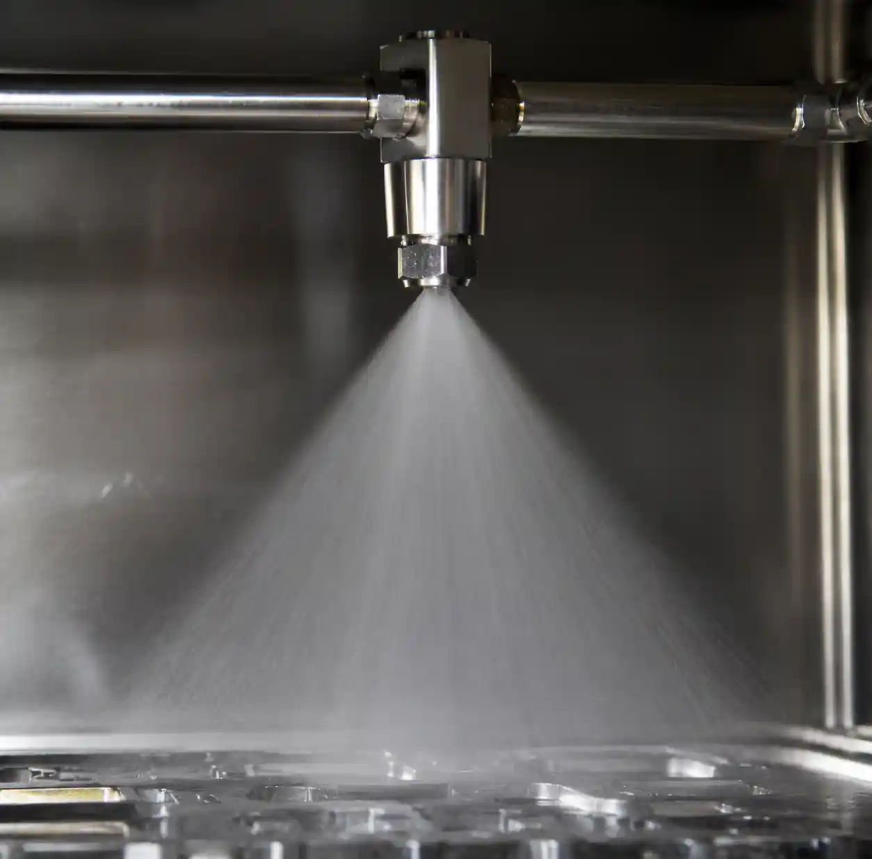
Most cleaning systems we audit suffer from "coverage gaps"—areas where spray overlap is either excessive (wasting water) or insufficient (requiring longer cycles or higher flow to compensate). This happens because nozzles are picked based on connection size or what's in stock, not on spray geometry matched to the job.
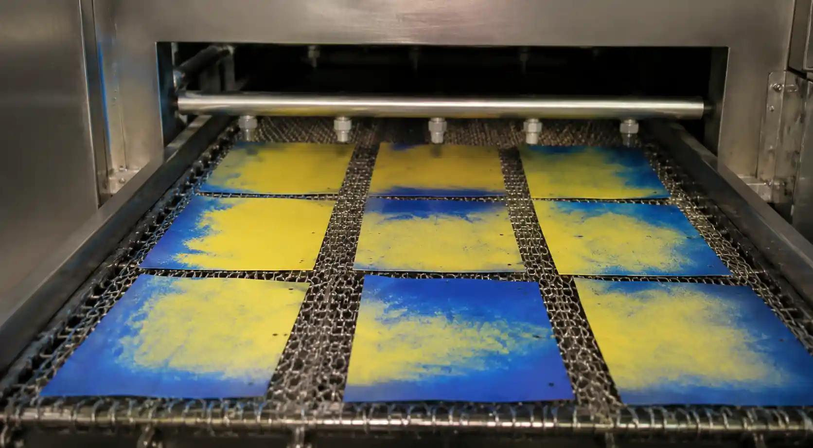
Take a typical conveyor washer with eight full cone nozzles at 5 GPM each, 40 PSI: 40 GPM total. But when we map actual coverage with water‑sensitive paper, only 60–65% of the part surface gets adequate impact. The rest needs extended cycle time, effectively doubling water consumption for complete cleaning.
Root causes we see repeatedly:
- Wrong spray angle: A 90° full cone 18 inches from target gives a 31‑inch circle. If parts are 12 inches wide, 40% of spray misses entirely.
- Excessive pressure: Doubling pressure from 40 to 80 PSI only increases flow by 41% (Q = K√P)—diminishing returns while wasting water and energy.
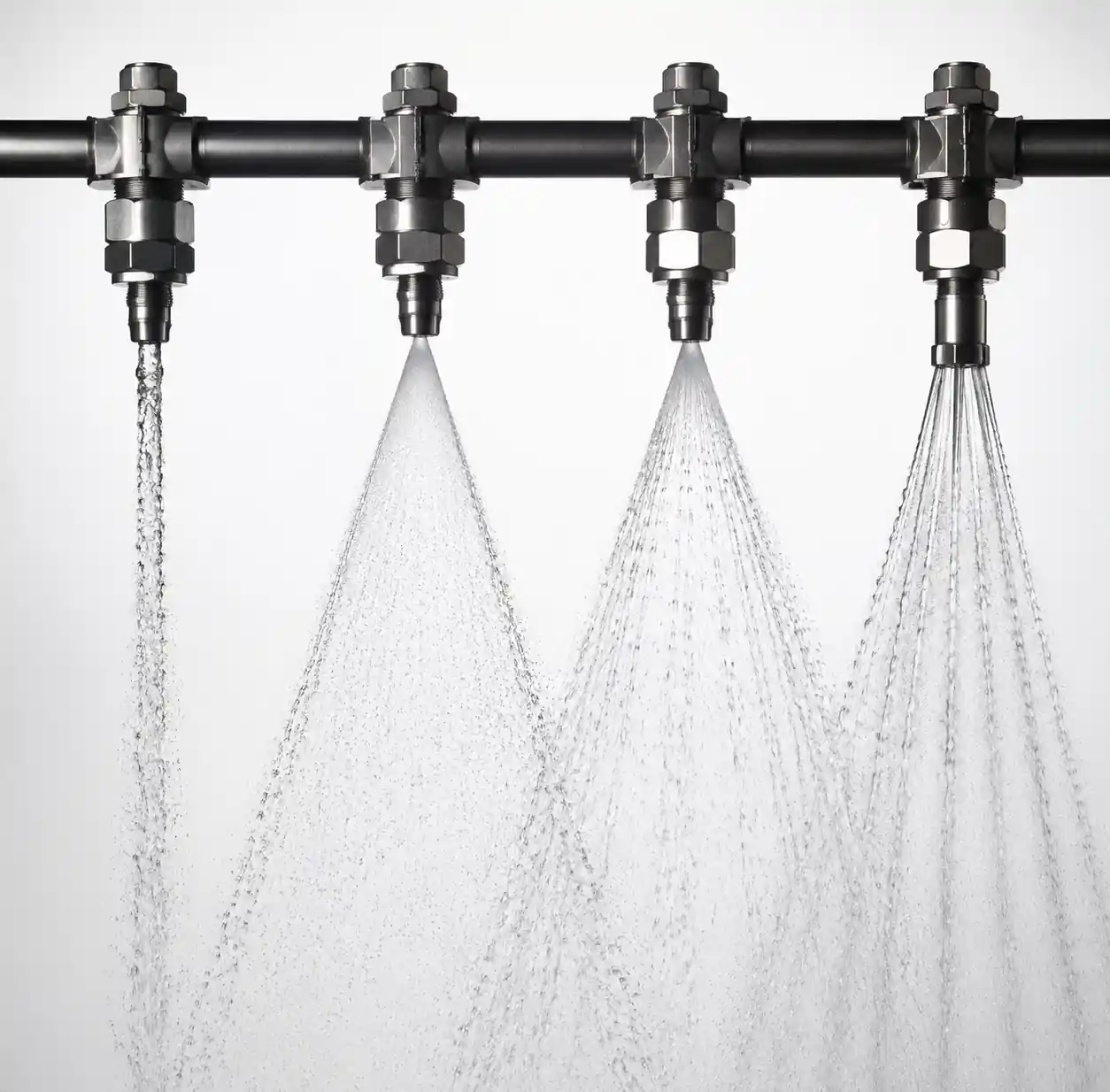
- Wrong nozzle type: Full cones spread flow evenly, but flat fans or hollow cones concentrate flow where needed.
Economic impact: A three‑shift operation running 6,000 h/yr at 40 GPM with $6/1,000 gal all‑in cost, reducing to 28 GPM saves $4,320/yr per machine. Payback often under 3 months when proper nozzles cost $800–1,200.
2. Critical Parameters for Water-Efficient Cleaning
Water reduction requires balancing four interdependent parameters.
2.1 Impact Force (Cleaning Power)
F = 0.0527 × Q × √P (F in lbf, Q in GPM, P in PSI).
From our testing, light soils need 0.15–0.30 lbf; heavy cutting fluids need 0.40–0.80 lbf. You can reduce flow if you optimize pressure—impact force depends on both.
2.2 Droplet Size and Coverage Uniformity
For flat surfaces, target 400–800 µm (Dv0.5) droplets. For blind holes, 200–400 µm works better. Droplets below 150 µm lose momentum quickly and evaporate in heated tanks—wasting water and energy.
2.3 Spray Angle and Standoff Distance
Coverage diameter = 2 × standoff × tan(angle/2).
For a 65° flat fan at 12‑inch standoff, coverage is about 14 inches. Match coverage to part width with 10–15% overlap. Avoid defaulting to 80° or 110°—narrower angles (40–65°) concentrate flow.
2.4 Cycle Time vs. Flow Rate
Water‑soluble coolants need 0.08–0.15 gal/ft²; cutting oils need 0.15–0.25 gal/ft². You can use high flow + short cycle or low flow + longer cycle—find the balance that minimizes total water while maintaining throughput.
3. Nozzle Type Selection for Cleaning Applications
| Nozzle Type | Spray Pattern | Best Use Cases | Typical Flow Savings vs. Full Cone | Limitations |
|---|---|---|---|---|
| Flat Fan | Elliptical, concentrated in center plane | Flat surfaces, conveyor parts, sheet metal, PCBs | 25–35% | Poor on complex 3D geometries |
| Full Cone | Circular, even distribution | General parts washing, tank interiors, large irregular parts | Baseline (0%) | Overspray on small/narrow parts |
| Hollow Cone | Ring‑shaped, concentrated at periphery | Cooling, tank bottoms, cylindrical parts | 15–25% | Weak center coverage |
| Flat Jet (0°) | Thin, high‑impact stream | Spot cleaning, weld slag, heavy deposits | 40–50% | Requires precise targeting, slow for large areas |
| Air Atomizing | Very fine droplets, large coverage | Rinse cycles, coating removal, delicate surfaces | 30–45% | Needs compressed air (added energy cost) |
Selection logic: For flat/slightly curved parts → flat fan (50–65°). For complex 3D → mix full cone + flat fan. For cylindrical → hollow cone. For heavy soils → flat jet pre‑spray then flat fan.
4. Step-by-Step Water Reduction Methodology
Step 1: Document Current Baseline
Measure total GPM (flow meter), pressure at nozzles, cycle time, part dimensions, current nozzle specs, and water per part. Calculate gallons per square foot—that's your baseline.
Step 2: Map Current Spray Coverage
Use water‑sensitive paper or flour dusting. Look for gaps, overspray, and overlap zones. We typically find 30–45% of spray volume lands outside the part—immediate waste.
Step 3: Calculate Required Impact Force
Based on soil type, test with lower pressures/flows until cleaning fails. Use the impact equation to find minimum Q at various P. Often you can cut flow 20–30% by adjusting pressure.
Step 4: Design Optimal Nozzle Layout
- Pick nozzle type (see Section 3).
- Calculate spray angle to match part width + 10–15% overlap.
- Set standoff distance.
- Determine number of nozzles.
- Choose orifice size for target flow at optimal pressure (typically 30–60 PSI).
Step 5: Specify Nozzle Materials for Longevity
Worn nozzles drift flow upward—undoing your savings.
| Material | Relative Cost | Typical Service Life | Best Applications |
|---|---|---|---|
| Brass | 1.0× | 8–15 months | Clean water, neutral pH, no abrasives |
| 303 Stainless | 1.3× | 12–20 months | Mildly alkaline wash, low abrasives |
| Hardened Stainless (17‑4PH) | 2.0× | 18–30 months | Acidic/alkaline, moderate abrasives |
| Alumina Ceramic | 3.5× | 36–60 months | High pH, abrasive slurries, acidic solutions |
| Silicon Carbide | 4.5× | 48–72 months | Extreme wear, abrasive media |
Economic note: Nozzle wear increases flow 15–25% before visible damage. If you cut flow 30% but nozzles wear out in 8 months, you lose half your savings. Invest in the right material upfront.
Step 6: Test and Validate
Install new nozzles, verify flow rate, coverage uniformity (water‑sensitive paper), cleaning effectiveness, and adjust cycle time if needed.
5. Worked Example: Reducing Water in Automotive Parts Washer
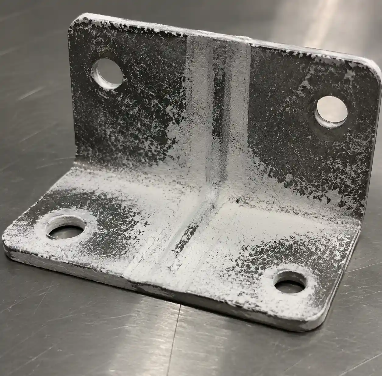
Application: Conveyor spray washer for stamped steel brackets (8″ wide, 12″ long), 6 ft/min.
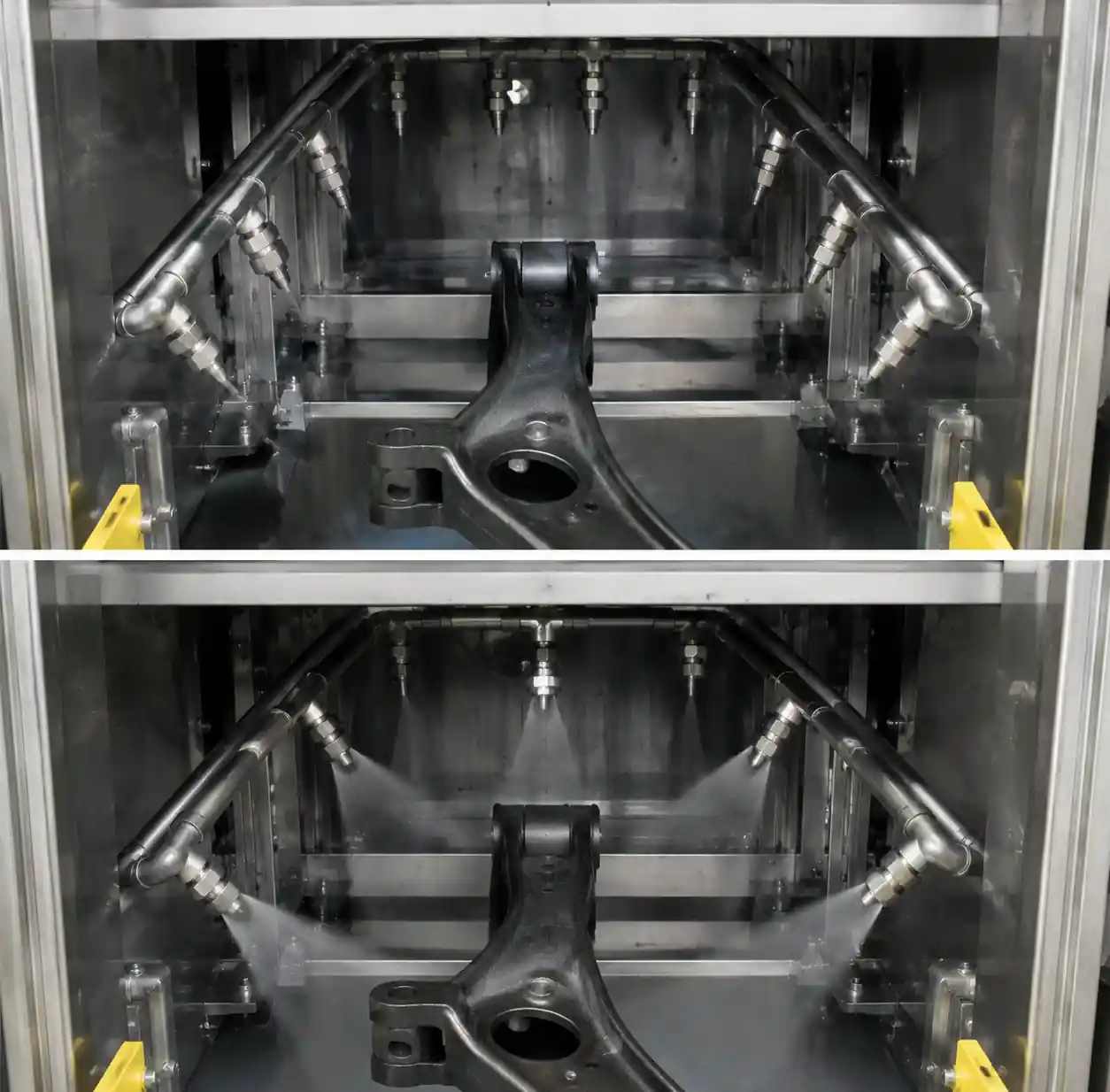
Baseline: 10 full cone nozzles, 80° angle, 4.2 GPM each at 45 PSI → 42 GPM total. Parts spend 80 sec in wash zone. Water per part: 0.56 gal.
Problem: Water‑sensitive paper showed 80° spray at 16″ standoff gave 29″ circles—parts only 8″ wide, ~72% of spray missed.
Optimization:
- Switched to 50° flat fan, 12″ standoff → 11″ coverage (adequate with overlap).
- Sized orifices for 2.8 GPM at 40 PSI.
- Checked impact: F = 0.0527 × 2.8 × √40 = 0.93 lbf (exceeds 0.40 minimum).
- Reduced nozzles from 10 to 8.
Results:
- Total flow: 22.4 GPM (47% reduction).
- Water per part: 0.30 gal (46% reduction).
- Cleaning pass rate: 98.2% vs. 98.5% baseline.
- Annual savings: 8.7 million gal → $52,200 at $6/1,000 gal.
- Payback: 1.8 months (retrofit cost $4,800).
6. Field Validation and Measurement Techniques
6.1 Coverage Mapping
- Water‑sensitive paper: Yellow turns blue where wetted. Cost $20–40/test.
- Flour dusting: Coat parts with flour; unwashed areas show gaps. Cost negligible.
- Impact force gauge: Use spring scale at part position—verify force threshold. Cost $100–300.
6.2 Ongoing Monitoring
Install a flow meter ($200–600). Record monthly—when flow increases 10–15% above baseline, replace nozzles.
6.3 Nozzle Wear Inspection
Inspect every 6–12 months. Look for enlarged orifice, rounded edges, distorted pattern, or flow 15% above spec. Replace immediately—one worn nozzle flowing 20% high can offset savings from two good ones.
7. Common Mistakes That Increase Water Waste
Mistake 1: Over‑pressurizing to compensate for wrong nozzle type
Pressure increase raises flow only modestly and doesn't fix coverage gaps. Fix the nozzle first, then optimize pressure.
Mistake 2: Using stock spray angles without geometry analysis
80° or 110° nozzles are easy to grab, but most parts under 18″ wide do better with 40–65° angles. Stock the right ones—payback is fast.
Mistake 3: Ignoring nozzle wear until visible
Flow can creep up 15–25% before you see pattern distortion. Schedule periodic flow checks and replacements (12–24 mo for brass/SS, 36–48 mo for ceramics).
Mistake 4: Single nozzle type for all surfaces
Mix flat fans for flat areas, full cones for general coverage, and flat jets for heavy deposits. This cuts total flow 20–30% and improves uniformity.
Mistake 5: Not validating coverage after installation
If you don't map coverage, you don't know if you actually succeeded. Always run water‑sensitive paper or flour tests—40% of installs need fine‑tuning.
8. FAQ
Q: Can I achieve 30% reduction in any cleaning application?
Not always. Largest savings (30–50%) occur in systems using full cones on flat parts. Complex 3D geometries typically see 15–25%. Tank washing often hits 20–30%. Results depend on your starting point and part complexity.
Q: Does reducing flow increase cycle time and reduce throughput?
Only if you drop below the required impact force. In ~70% of our projects, cycle time stays same or decreases slightly. In 30%, we extend cycle 10–20% but still reduce total water volume 20–30%.
Q: What's the typical payback period for nozzle optimization?
For two‑ or three‑shift operations, payback is 2–6 months. Single‑shift: 6–12 months. Median across all our projects is 4.5 months.
Q: How many nozzles do I need after optimization?
Calculate coverage width per nozzle from angle and standoff. Divide part width by that, add 10–15% overlap for adjacent nozzles. For conveyors, divide wash zone length by (speed × minimum dwell) to get total count.
Q: Can I reduce rinse water too?
Yes—rinses often use even higher flows but need lower impact. We typically cut rinse flow 35–45% using air atomizing or fine‑spray flat fan nozzles, which wet surfaces thoroughly with less water.
9. Conclusion
Systematic nozzle optimization can cut water consumption by roughly 30% in most facilities. The core steps: map current coverage to find waste, select nozzles matched to part geometry, calculate correct angles and flows, and validate with field tests. The biggest gains come from eliminating overspray via proper type and angle; secondary gains from pressure and count optimization; and material choices ensure savings last. For a deeper dive into the 5 critical parameters that determine nozzle performance—flow rate, pressure, spray angle, material wear, and droplet size—see our detailed guide. And if your application involves tank cleaning, our rotary tank cleaning nozzle selection guide offers additional insights on free‑spinning vs controlled rotation designs.