



Frequent Nozzle Clogging? Filtration and Nozzle Selection Solutions for Industrial Circulating Water Systems
Table of Contents
- 1. 1. Introduction: The True Cost of Nozzle Clogging
- 2. 2. Why Circulating Water Systems Are Prone to Clogging
- 2.1. 2.1 Sources of Suspended Solids
- 2.2. 2.2 Where Clogging Occurs
- 2.3. 2.3 Impact on Spray Performance
- 3. 3. Filtration Strategy: Matching Filter Mesh to Nozzle Orifice
- 3.1. 3.1 The 4:1 Filtration Rule
- 3.2. 3.2 Filter Types and Selection
- 3.3. 3.3 Filtration Economics
- 4. 4. Nozzle Selection for Clog Resistance
- 4.1. 4.1 Nozzle Type Comparison for Clogging Resistance
- 4.2. 4.2 Free-Passage Nozzle Designs
- 4.3. 4.3 Material Selection for Abrasive Environments
- 5. 5. Worked Example: Cooling Tower Filtration and Nozzle Sizing
- 5.1. 5.1 System Parameters
- 5.2. 5.2 Solution Design
- 5.3. 5.3 Results
- 6. 6. Troubleshooting Persistent Clogging Issues
- 7. 7. FAQ
- 7.1. Q: Can I just increase pressure to compensate for partial clogging?
- 7.2. Q: How do I tell if a nozzle is clogged or worn out?
- 7.3. Q: Should I use self-cleaning nozzles?
- 7.4. Q: What particle concentration is acceptable without filtration?
- 7.5. Q: How often should I replace filter elements?
- 8. 8. Conclusion
1. Introduction: The True Cost of Nozzle Clogging
In industrial circulating water systems – gas cooling, quenching, dust suppression, evaporative cooling – nozzle clogging is a headache that keeps giving. Spray patterns go bad, cooling gets uneven, hotspots show up, maintenance crews get pulled off other work, and sometimes production stops entirely. From field work across steel mills, chemical plants, and data center cooling towers, we figure 60-70% of spray performance complaints trace back to bad filtration or poor nozzle selection for the solids in the water. This guide walks through a systematic fix: match your filtration to your nozzle orifice, pick clog-resistant nozzle designs, and calculate whether the investment in better filtration actually pays off. For a full range of industrial cleaning nozzles and spray solutions, see our application overview.
2. Why Circulating Water Systems Are Prone to Clogging
2.1 Sources of Suspended Solids
Circulating water isn't clean. Common culprits: scale particles from heat exchangers (calcium carbonate, calcium sulfate), corrosion products (iron oxide, copper oxide), biological growth (algae, biofilm flakes), airborne debris in open systems (dust, pollen), and process carryover (mineral fines, fibers). Particle sizes typically run 10-500 microns, with the 50-200 micron range being the most problematic for standard nozzles.
2.2 Where Clogging Occurs
Clogging mechanisms vary by nozzle design. In hydraulic nozzles, particles lodge at the orifice entrance or in the swirl chamber vanes. In air atomizing nozzles, blockage hits the small liquid orifice (often 0.5-1.5 mm) or the annular air cap slots. In spiral nozzles, the helical groove traps fibrous material. Key point: the smallest flow restriction in the nozzle determines clogging vulnerability – not the thread size or inlet connection. When comparing different designs, our spiral vs full cone nozzles guide breaks down the internal flow path differences that affect clogging sensitivity.
2.3 Impact on Spray Performance
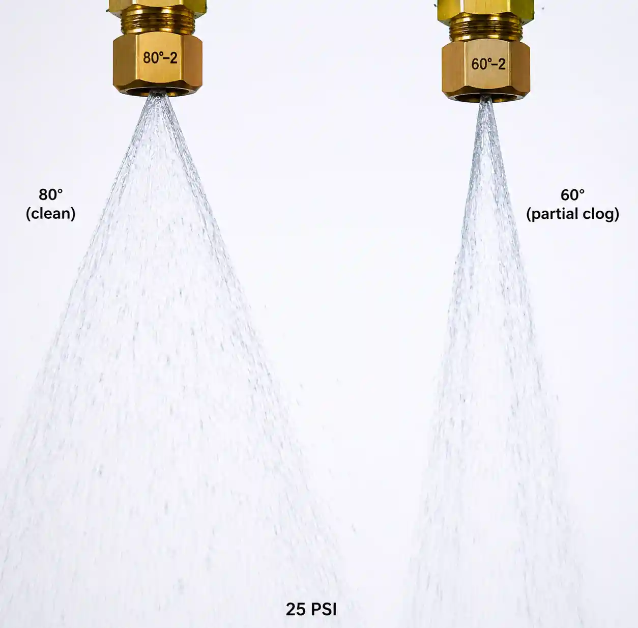 Comparison of spray pattern from clean nozzle versus partially clogged nozzle showing reduced spray angle
Partial clogging narrows spray angle – 80° down to 60° or less – reducing coverage and creating dry spots. Flow rate drops off the Q = k√P curve due to added resistance. Impact force and droplet distribution shift unpredictably. In cooling, uneven spray causes thermal shock and poor heat transfer. In cleaning, missed zones mean rework or rejects.
3. Filtration Strategy: Matching Filter Mesh to Nozzle Orifice
3.1 The 4:1 Filtration Rule
Rule of thumb: filter mesh opening should be ≤ 1/4 of the nozzle's smallest internal flow passage. For a 2.0 mm orifice, use a filter with max 500 micron (0.5 mm) openings. This balances clog prevention with reasonable filter maintenance. Tighter filtration (10:1 ratio) makes sense for high-value processes or where downtime costs over $1000/hour.
3.2 Filter Types and Selection
| Filter Type | Mesh Range (microns) | Flow Capacity | Pressure Drop | Maintenance | Best Use Case |
|---|---|---|---|---|---|
| Y-strainer | 500-2000 | High | Low (0.5-2 psi clean) | Manual cleanout | Coarse pre-filtration, large orifice nozzles (>3 mm) |
| Basket strainer | 250-1000 | Very high | Low (1-3 psi clean) | Removable basket | Main-line filtration for full cone / hollow cone |
| Automatic backflush | 50-500 | Medium-high | Medium (3-8 psi) | Self-cleaning | Fine filtration for flat fan, air atomizing |
| Disk filter | 20-200 | Medium | Medium (5-10 psi) | Disassembly required | Ultra-fine for precision coating, minimum flow |
Pressure drop watch: Dirty filters can hit 15-30 psi drop before breakthrough. Monitor ΔP across the filter and set a cleaning threshold (typically 10 psi above clean baseline).
3.3 Filtration Economics
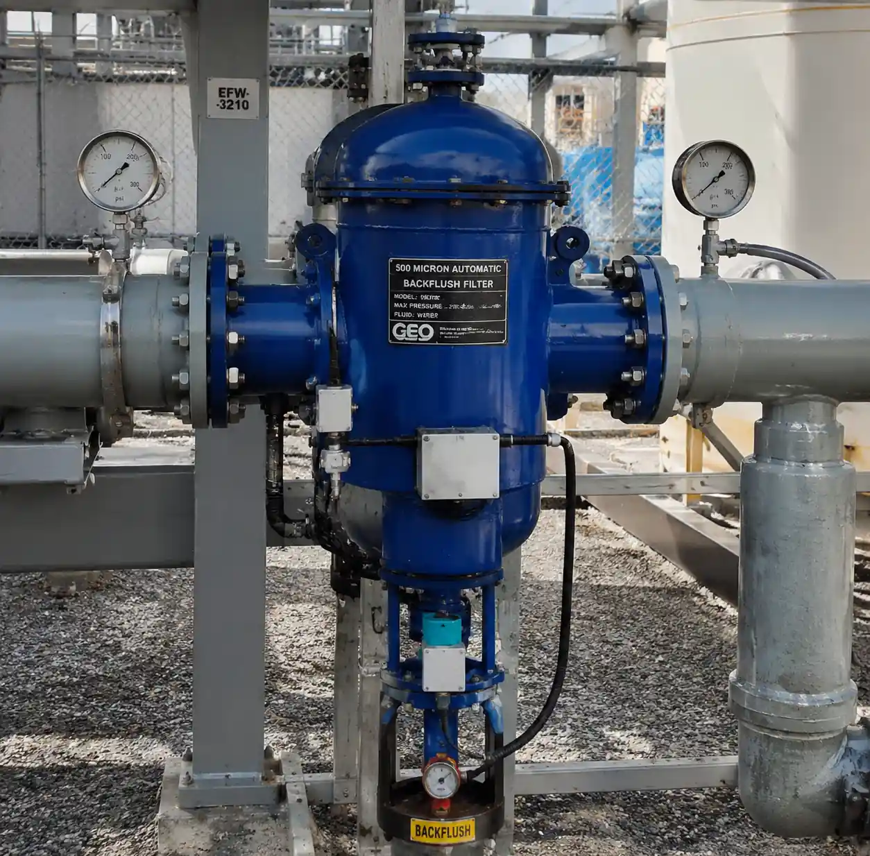 Industrial automatic backflush filter installed in circulating water line with pressure gauges
Run the numbers over 12 months:
- Option A (no filtration): Nozzle replacement cost × frequency + downtime cost
- Option B (filtration): Filter capital + maintenance labor + pressure drop energy penalty
From cooling tower cases, automatic backflush filters paid back in 4-7 months by cutting nozzle replacement from quarterly to annual and eliminating two unplanned shutdowns.
4. Nozzle Selection for Clog Resistance
4.1 Nozzle Type Comparison for Clogging Resistance
| Nozzle Type | Min Orifice (mm) | Clog Sensitivity | Flow Passage | Suitable for Suspended Solids |
|---|---|---|---|---|
| Full cone (axial vane) | 1.5-25 | Low | Large central orifice + radial vanes | Up to 500 ppm |
| Hollow cone (tangential) | 2.0-20 | Low-medium | Tangential inlet slots + central orifice | Up to 300 ppm |
| Flat fan (internal vane) | 0.8-12 | Medium-high | Narrow internal slot + vane insert | Up to 150 ppm, needs filtration |
| Air atomizing (internal mix) | 0.5-2.0 | Very high | Tiny liquid orifice + air passages | <50 ppm, filtration mandatory |
| Spiral (helical groove) | 3.0-25 | Low | Wide helical channel | Up to 800 ppm, good for slurries |
Key takeaway: When suspended solids exceed 200 ppm or contain fibrous material, go with full cone or spiral nozzles with orifice ≥ 3 mm. These tolerate particle passage without clogging, trading finer spray for uptime.
4.2 Free-Passage Nozzle Designs
Some manufacturers offer "free-passage" or "non-clog" variants with smooth, unobstructed flow paths – no internal vanes or swirl chambers, just orifice geometry to shape the spray. Trade-offs: less uniform spray and wider droplet distribution. But in heavily contaminated systems (mine water, wastewater cooling), the reliability gain is worth it. We've seen free-passage nozzles run 18+ months in steel mill descaling where standard flat fans clogged within weeks.
4.3 Material Selection for Abrasive Environments
Clogging and wear often go together. In abrasive service, pair clog-resistant design with wear-resistant materials:
- Silicon carbide: Hardness ~2500 HV, 8-12× longer life than stainless in coal slurry.
- Tungsten carbide: Hardness ~1500 HV, best for high-pressure (>1000 psi) abrasive sprays.
- 17-4 PH hardened stainless: Cost-effective baseline, 2-3× life vs 316 SS.
Run the math: if a silicon carbide nozzle costs 5× more but lasts 10× longer, cost per operating hour is half that of stainless – plus you save on changeout labor.
5. Worked Example: Cooling Tower Filtration and Nozzle Sizing
5.1 System Parameters
- Application: Evaporative cooling tower, open-loop circulating water
- Flow: 500 GPM total
- Pressure: 25 psi at nozzle inlet
- Water quality: 300 ppm suspended solids (scale, algae, corrosion), 50-400 micron particle size
- Coverage: 20 ft × 20 ft spray deck
- Existing problem: Flat fan nozzles (1.2 mm orifice) clog every 2-3 weeks
5.2 Solution Design
Step 1: Switch to full cone – Select full cone nozzles with 3.0 mm orifice, 60° spray angle. These tolerate 300 ppm solids without constant clogging.
Step 2: Calculate nozzle count – Each 60° full cone at 25 psi produces about 8 GPM (check manufacturer's flow chart: Q = k√P). Number needed = 500 GPM ÷ 8 = 63 nozzles.
Step 3: Determine spacing – For 60° angle at 6 ft mounting height, coverage diameter ≈ 6 × tan(30°) × 2 ≈ 7 ft. Grid spacing = 7 ÷ √2 ≈ 5 ft for overlap. 20×20 area needs 5×5 = 25 minimum; with 63 available, arrange 8×8 at 2.5 ft spacing for redundancy.
Step 4: Install basket strainer – Use 500 micron (3.0 mm ÷ 4 = 0.75 mm ≈ 750 micron, round down to 500 for safety). Size for 500 GPM at <5 psi clean drop. Clean when ΔP hits 12 psi.
Step 5: Verify pressure – With 8 psi filter drop, pump needs 25 + 8 + piping losses ≈ 38 psi at header. Check pump curve.
5.3 Results
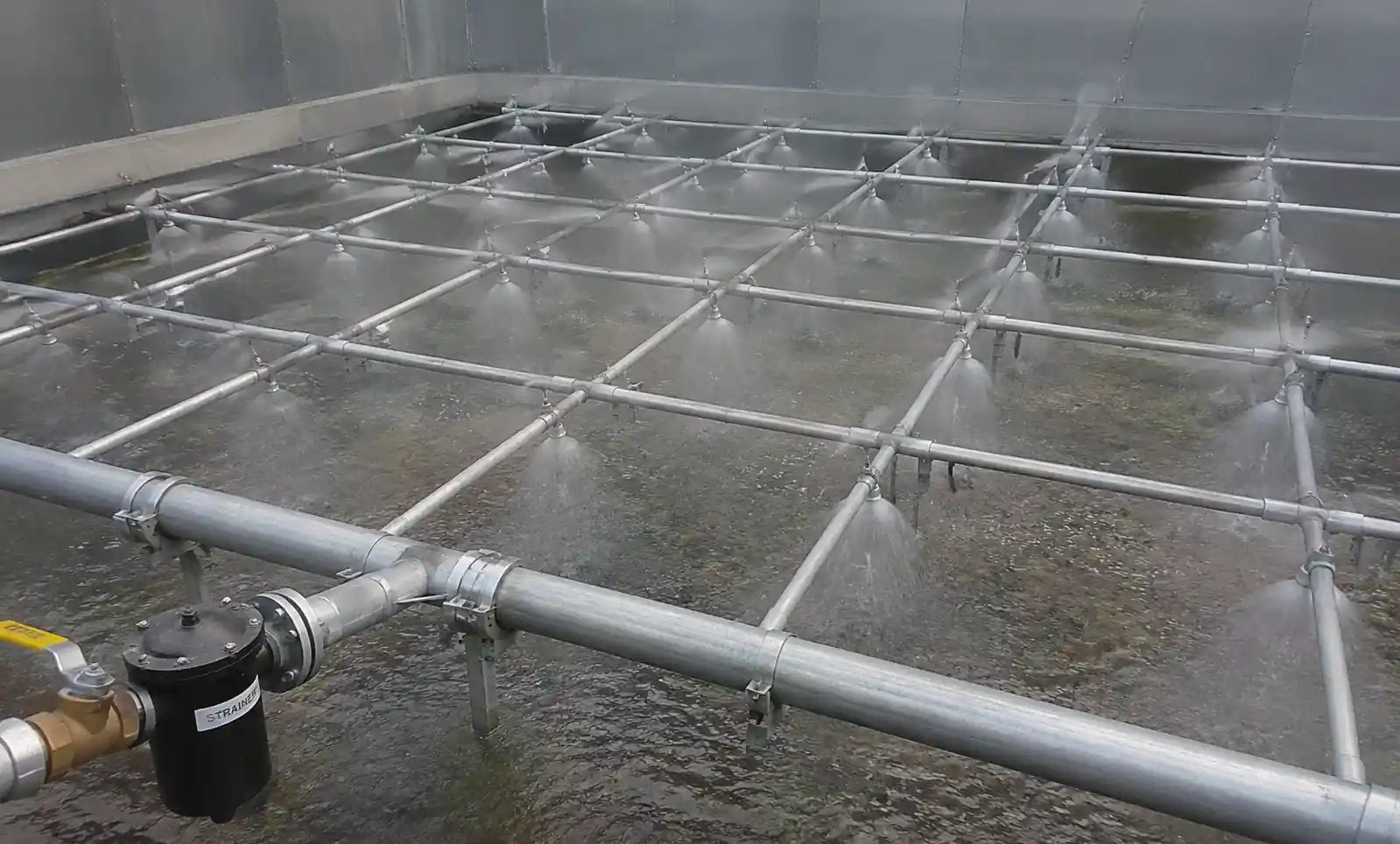 Cooling tower spray deck with full cone nozzles arranged in systematic grid pattern
After retrofit, the cooling tower ran 9 months without a single nozzle changeout (versus 18 changeouts in the previous 9 months). Basket filter needed weekly cleaning initially, dropping to bi-weekly after water treatment adjustments. Total savings: $14,000 in labor and nozzle inventory, plus avoided downtime.
6. Troubleshooting Persistent Clogging Issues
| Symptom | Probable Root Cause | Diagnostic Check | Corrective Action |
|---|---|---|---|
| Nozzles clog within hours despite filtration | Filter bypassing or damaged mesh | Inspect element for tears; check bypass valve | Replace element; disable or reduce bypass setpoint |
| Only certain nozzles clog, others fine | Uneven flow distribution, some nozzles see higher velocity | Measure flow at each manifold branch; check header sizing | Rebalance piping; increase header diameter to keep velocity <5 ft/s |
| Clogging worse after system restart | Loose scale and biofilm dislodged during shutdown | Flush system with strainer in place before starting | Implement startup flush protocol; consider biocide treatment |
| Fibrous material wraps around nozzle inlet | Long fibers not captured by mesh filter | Switch to bag filter or add upstream screening | Install 1 mm bag filter; improve debris removal upstream |
| Clogging frequency increases over time | Corrosion or scale formation accelerating | Trend water chemistry (pH, conductivity, iron, hardness) | Adjust inhibitor dosing; increase blowdown rate |
Field tip: When troubleshooting, pull a clogged nozzle and photograph the deposit under magnification. Particle morphology tells the story – sharp angular fragments = scale or mineral; soft organic clumps = biofilm; rust-red staining = corrosion. Share images with your water treatment vendor for targeted chemistry adjustments.
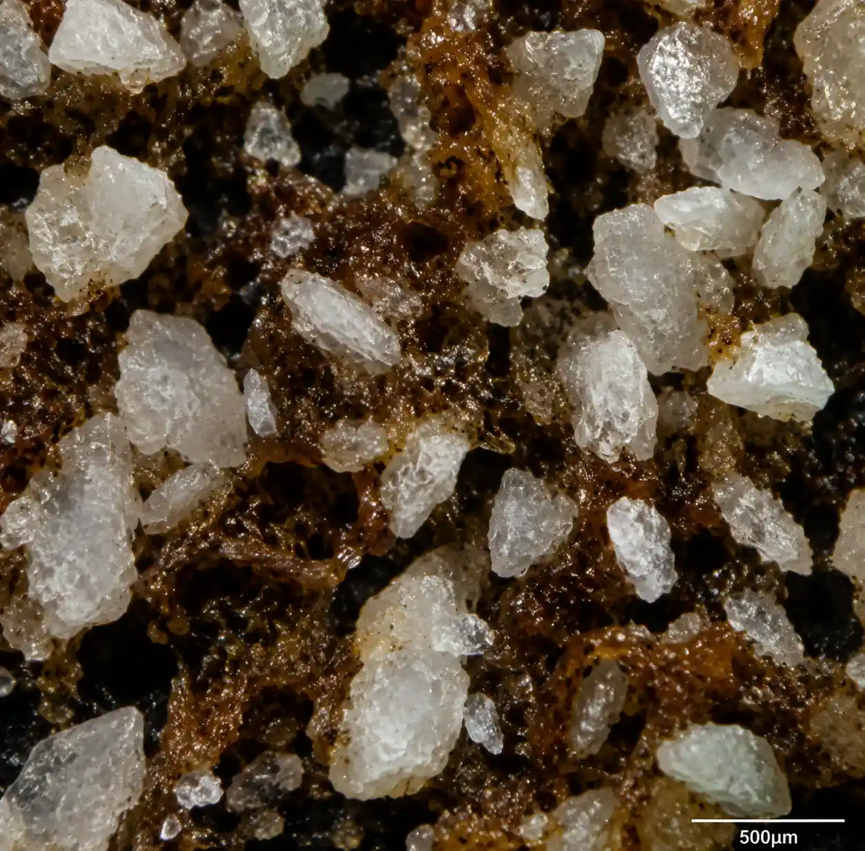 Magnified view of clogging deposits removed from nozzle showing scale particles and biofilm
7. FAQ
Q: Can I just increase pressure to compensate for partial clogging?
No. Raising pressure may restore flow temporarily, but it accelerates erosion at the clog point, enlarges the orifice asymmetrically, and makes spray uniformity worse. Fix the root cause – clogging – not the symptom.
Q: How do I tell if a nozzle is clogged or worn out?
Measure flow at fixed pressure. If flow < 90% of nominal, suspect either. Pull and inspect: clogged orifice shows debris; worn orifice is smooth and oversized. Use a pin gauge to check orifice diameter against original spec.
Q: Should I use self-cleaning nozzles?
Self-cleaning nozzles (with internal check valves or reverse-flow purge) work well for intermittent spray where you can reverse flow periodically. In continuous systems, they add complexity and potential leak points. We recommend them only when filtration is impractical – mobile gear or temporary setups.
Q: What particle concentration is acceptable without filtration?
For robust nozzles (full cone, spiral, orifice ≥3 mm), up to 500 ppm TSS is manageable if particles are <1 mm and non-fibrous. Above 500 ppm or with fibrous content, filtration becomes mandatory regardless of nozzle type.
Q: How often should I replace filter elements?
Replace when cleaning frequency exceeds twice per week or when ΔP can't be restored below 10 psi after cleaning. Typical service life: 6-12 months for automatic backflush filters, 3-6 months for manual basket strainers in heavy service.
 Engineering schematic showing complete circulating water system with filtration and spray nozzles
8. Conclusion
Frequent clogging isn't something you have to live with. Match your filtration to 1/4 of your nozzle orifice diameter, pick nozzle designs with big, straight-through flow paths, and you'll cut maintenance headaches by 70-90%. The math usually works out – most plants see payback inside a year. Start with your worst-performing header, run the numbers, and validate with a pilot before rolling out across the whole system. For more on nozzle fundamentals, check out our guide on the 5 critical parameters you cannot ignore.