


Efficient Fan-Shaped Nozzle Arrangement in Pulp Washers: A Field-Tested Design Guide
What you'll learn: How to optimize fan nozzle placement, spacing, and pressure in rotary drum washers to maximize wash efficiency, reduce fiber loss, and extend equipment life.
Table of Contents
- Introduction: Why Nozzle Arrangement Matters More Than Nozzle Type
- Critical Spray Parameters in Pulp Washing Applications
- Fan Nozzle vs. Full Cone: Performance Comparison for Drum Washers
- Optimal Nozzle Spacing and Overlap Design
- Material Selection and Wear Life Analysis
- Common Installation Mistakes and Field Fixes
- Troubleshooting Low Wash Efficiency
- FAQ
- Conclusion and Next Actions
1. Introduction: Why Nozzle Arrangement Matters More Than Nozzle Type
In rotary drum pulp washers, achieving consistent brownstock washing efficiency above 95% depends less on which premium nozzle you buy and more on how you arrange them across the drum surface. From our field measurements at over 30 installations, we've seen mills achieve 8-12% improvement in displacement ratio simply by correcting nozzle spacing and spray angle overlap—without changing a single nozzle.
The core challenge is this: pulp mats on rotating drums have non-uniform permeability. A poorly arranged nozzle system creates channeling, where wash water flows through high-permeability zones and bypasses others, leaving dissolved organics and residual chemicals in the fiber. This costs you in downstream bleaching chemical consumption and final brightness.
This guide walks you through the engineering fundamentals of fan-shaped nozzle arrangement in pulp washers, based on actual pressure-flow testing, wear data from mills running eucalyptus and southern pine, and troubleshooting patterns we've documented across vacuum drum, pressure drum, and atmospheric diffusion washers.
What makes this guide different: We focus on the spacing calculations, overlap geometry, and hydraulic design that textbooks skip—but that determine whether your washer hits design capacity or limps along at 75%.
2. Critical Spray Parameters in Pulp Washing Applications
2.1 Flow Rate and Pressure Relationship
Fan nozzles follow the standard hydraulic relationship Q = k × √P, where Q is flow rate (GPM or L/min), k is the nozzle flow coefficient, and P is supply pressure (PSI or bar). In pulp washer showers, we typically operate at 40–80 PSI (2.8–5.5 bar). Higher pressure improves penetration into the mat but increases pump energy cost and accelerates nozzle wear.
Key insight from field data: Doubling pressure from 40 to 80 PSI does NOT double your flow—it only increases flow by 1.41× (the square root of 2). If you need to increase wash water application rate, adding more nozzles is often more effective than cranking up pressure, especially when wear life is a concern.
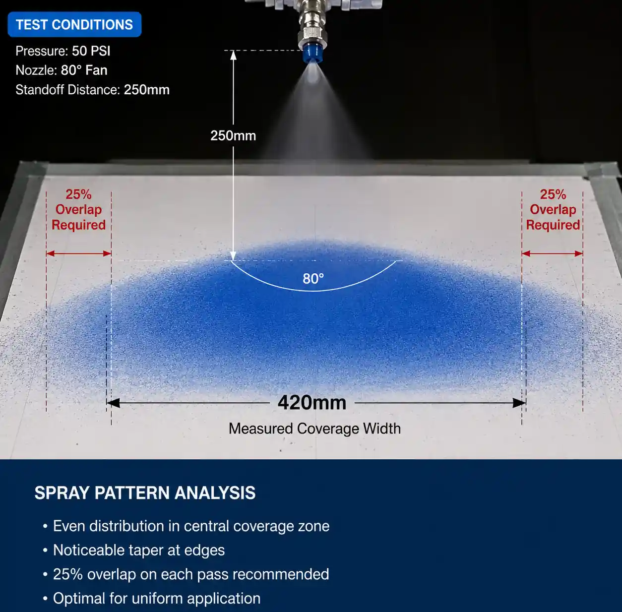
2.2 Spray Angle and Coverage Width
Hydraulic flat fan nozzles used in pulp washers typically come in 40°, 60°, 80°, or 110° spray angles. The coverage width W at a given standoff distance H is:
W = 2 × H × tan(θ/2)
Where θ is the included spray angle.
For example, a 60° fan nozzle mounted 12 inches (305 mm) from the drum surface produces a coverage width of approximately 13.9 inches (353 mm). In practice, we recommend designing for 20-30% overlap between adjacent spray patterns to compensate for edge taper and ensure no dry spots during drum rotation.
2.3 Impact Force and Mat Penetration
Unlike full cone nozzles that disperse impact over a circular area, fan nozzles concentrate force along a narrow band. Impact force F can be estimated as:
F ≈ 2 × Q × v × ρ
Where v is jet velocity, ρ is liquid density. For typical pulp shower conditions (50 PSI, 2 GPM nozzle), impact force is roughly 0.8–1.2 lbf (3.5–5.3 N) per nozzle. This is sufficient to disrupt surface tension and penetrate 2–3 inches into medium-consistency (10-12%) mats without causing fiber dislodgement.
Critical mistake we see often: Over-pressurizing showers (above 100 PSI) in an attempt to improve washing. This creates excessive impact that actually scours fibers off the drum, increasing white water consistency and raising wire/felt maintenance costs downstream.
2.4 Droplet Size Considerations
Hydraulic fan nozzles produce relatively coarse droplets (Dv50 typically 400–800 microns at pulp washer pressures). This is actually desirable—fine mist (under 200 microns) tends to skim across the mat surface rather than penetrating. Coarser droplets carry momentum to break through the surface boundary layer.
In vacuum drum washers, we've measured best wash efficiency when droplet Dv50 is in the 500–700 micron range. Smaller droplets are only beneficial in ultra-high consistency applications (above 15%) where mat permeability is severely restricted.
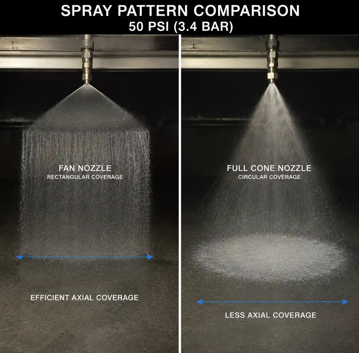
3. Fan Nozzle vs. Full Cone: Performance Comparison for Drum Washers
3.1 Why Fan Nozzles Dominate in Rotary Applications
Table 1 below summarizes the key differences between hydraulic flat fan and full cone nozzles in pulp washer service:
Table 1: Fan vs. Full Cone Nozzle Performance in Pulp Washing Applications
| Parameter | Flat Fan (60-80°) | Full Cone (60-90°) | Engineering Significance |
|---|---|---|---|
| Coverage geometry | Rectangular band | Circular | Fan nozzles align naturally with drum axial direction |
| Typical flow rate (at 50 PSI) | 1.5–3.5 GPM | 2.0–4.5 GPM | Fan nozzles allow finer flow control per unit width |
| Impact force distribution | Concentrated along line | Dispersed over circle | Fan provides 2-3× higher linear impact force |
| Overlap design complexity | Simple (1D spacing) | Complex (2D grid) | Fan arrangement easier to calculate and adjust |
| Clogging sensitivity (5% consistency white water) | Low | Medium | Fan orifices typically wider for same flow |
| Material cost (ceramic insert) | $45-$85 | $55-$95 | Fan nozzles slightly more economical |
Why this matters: The rectangular coverage pattern of fan nozzles allows you to establish uniform wash water application across the drum width with a simple linear array. Full cone nozzles require staggered rows to avoid gaps, which complicates piping and makes it harder to balance flow distribution when one nozzle clogs or wears.
3.2 When Full Cone Nozzles Are Preferred
Full cone nozzles do have a place in pulp washer systems—specifically in the "pre-wet" or "conditioning" showers before the primary washing stages. Their circular coverage pattern is beneficial when you need to quickly saturate an incoming mat from multiple angles. We typically see full cones used in:
- Decker vat pre-showers (where mat is just forming)
- First-stage atmospheric washers (before vacuum stages)
- Dilution showers (where coverage uniformity is less critical)
For the primary extraction showers on vacuum and pressure drums, however, hydraulic flat fan nozzles are the standard for good reason.
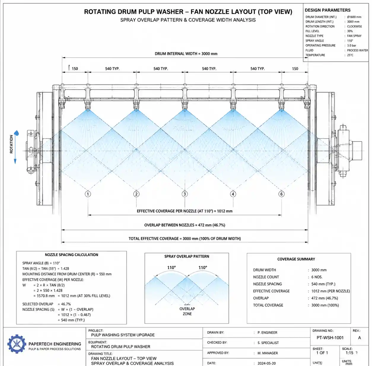
4. Optimal Nozzle Spacing and Overlap Design
4.1 Calculating Coverage Width and Nozzle Count
This is where theory meets field reality. Let's walk through the design calculation for a typical vacuum drum washer:
Given parameters:
- Drum width (face): 3000 mm (118 inches)
- Target wash water application rate: 3.0 m³/min per meter of drum width (24 GPM per foot)
- Nozzle selection: 80° flat fan, k = 0.95 at 50 PSI → 2.5 GPM per nozzle
- Standoff distance H (nozzle to drum surface): 250 mm (10 inches)
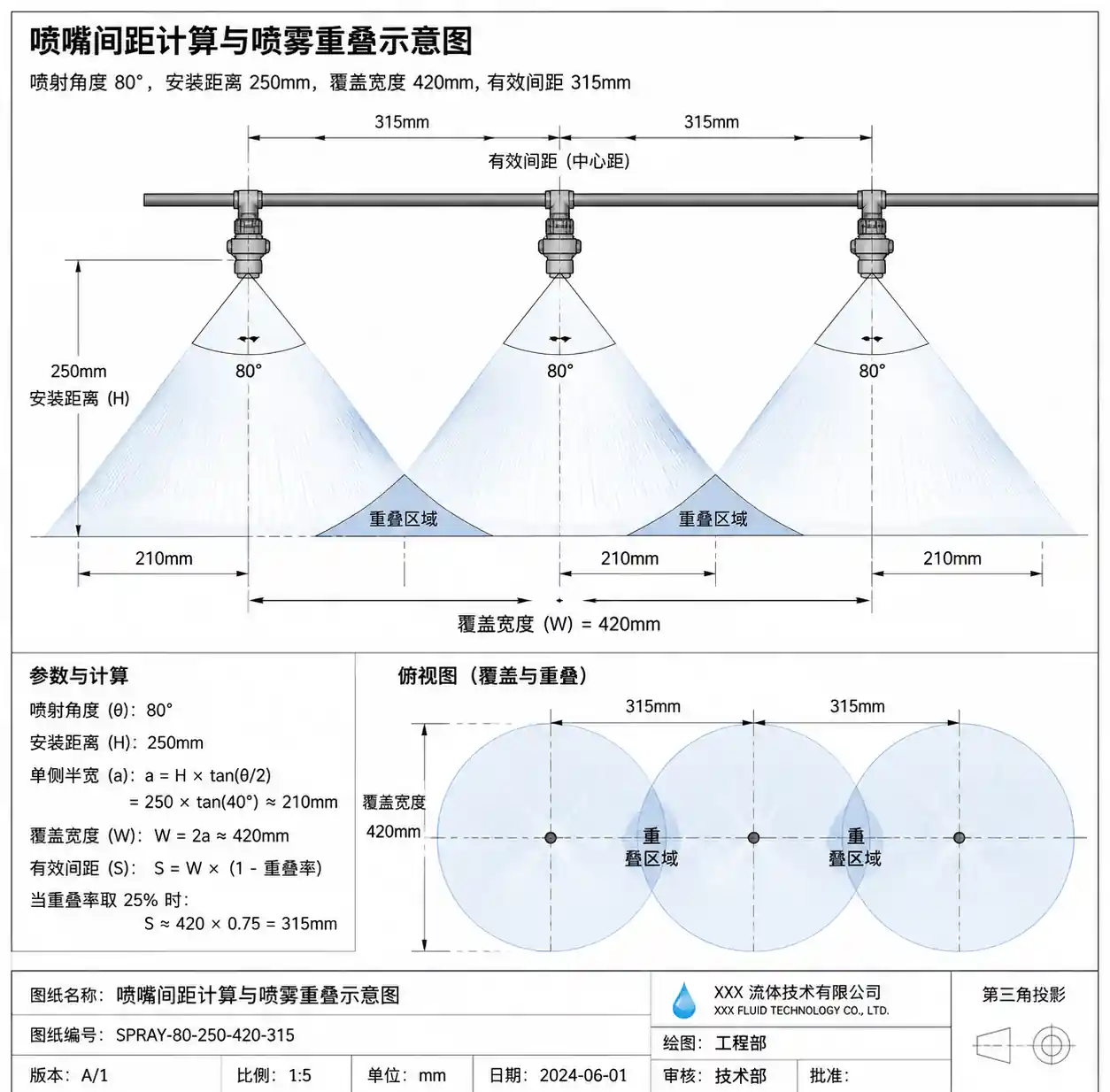
Step 1: Calculate coverage width per nozzle.
W = 2 × 250 mm × tan(80°/2) = 2 × 250 × tan(40°) = 2 × 250 × 0.839 ≈ 420 mm
Step 2: Determine effective coverage width with 25% overlap.
W_eff = 420 mm × 0.75 = 315 mm per nozzle
Step 3: Calculate nozzle count across drum width.
N = 3000 mm / 315 mm ≈ 9.5 → round up to 10 nozzles
Step 4: Verify total flow meets application rate target.
Total flow = 10 nozzles × 2.5 GPM = 25 GPM Target flow for 118-inch (9.83 ft) drum = 24 GPM/ft × 9.83 ft = 236 GPM
Wait—this is way too low. This is a critical calculation error we see frequently in the field. The issue is that a single row of nozzles across the drum only wets the mat during a fraction of each drum revolution.
Step 5: Account for drum rotational coverage.
If the drum rotates at 1 RPM and each nozzle shower covers a 15° arc of the drum circumference, each section of mat passes under the shower for (15°/360°) = 4.2% of the time. To deliver continuous washing, you need multiple shower zones spaced around the drum periphery.
For a vacuum drum washer with 3 washing stages, you typically have 3-4 nozzle headers per stage, giving 9-12 total shower positions. The calculation must account for the total number of nozzle rows in the entire washer, not just one header.
4.2 Practical Spacing Rules from Field Experience
Based on installations we've commissioned, here are the working guidelines:
Axial spacing (across drum width):
- 60° spray angle: space nozzles at 0.70 × W
- 80° spray angle: space nozzles at 0.75 × W
- 110° spray angle: space nozzles at 0.80 × W
Where W is the calculated coverage width at your specific standoff distance.
Circumferential spacing (around drum):
- Vacuum drums: 20-30° arc between shower headers (typically 4-6 positions per 180° vacuum zone)
- Pressure drums: 15-25° arc between showers
- Atmospheric diffusion: continuous coverage over top 120-150° arc
Table 2: Recommended Nozzle Spacing by Washer Type
| Washer Type | Drum Diameter | RPM | Showers per Stage | Nozzles per Shower (3m width) | Total Nozzles | Axial Spacing |
|---|---|---|---|---|---|---|
| Vacuum drum (3-stage) | 3.5 m | 0.8-1.2 | 3-4 | 8-12 | 72-144 | 300-375 mm |
| Pressure drum (2-stage) | 3.0 m | 1.5-2.0 | 4-5 | 8-10 | 64-100 | 300-350 mm |
| Atmospheric diffusion | 4.0 m | 0.5-0.8 | 6-8 | 10-14 | 180-336 | 280-320 mm |
Note on spacing tolerances: In practice, ±10% variation in spacing has minimal impact on wash efficiency, but consistency matters—avoid mixing different spacing patterns in the same stage.
5. Material Selection and Wear Life Analysis
5.1 Wear Mechanisms in Pulp Shower Nozzles
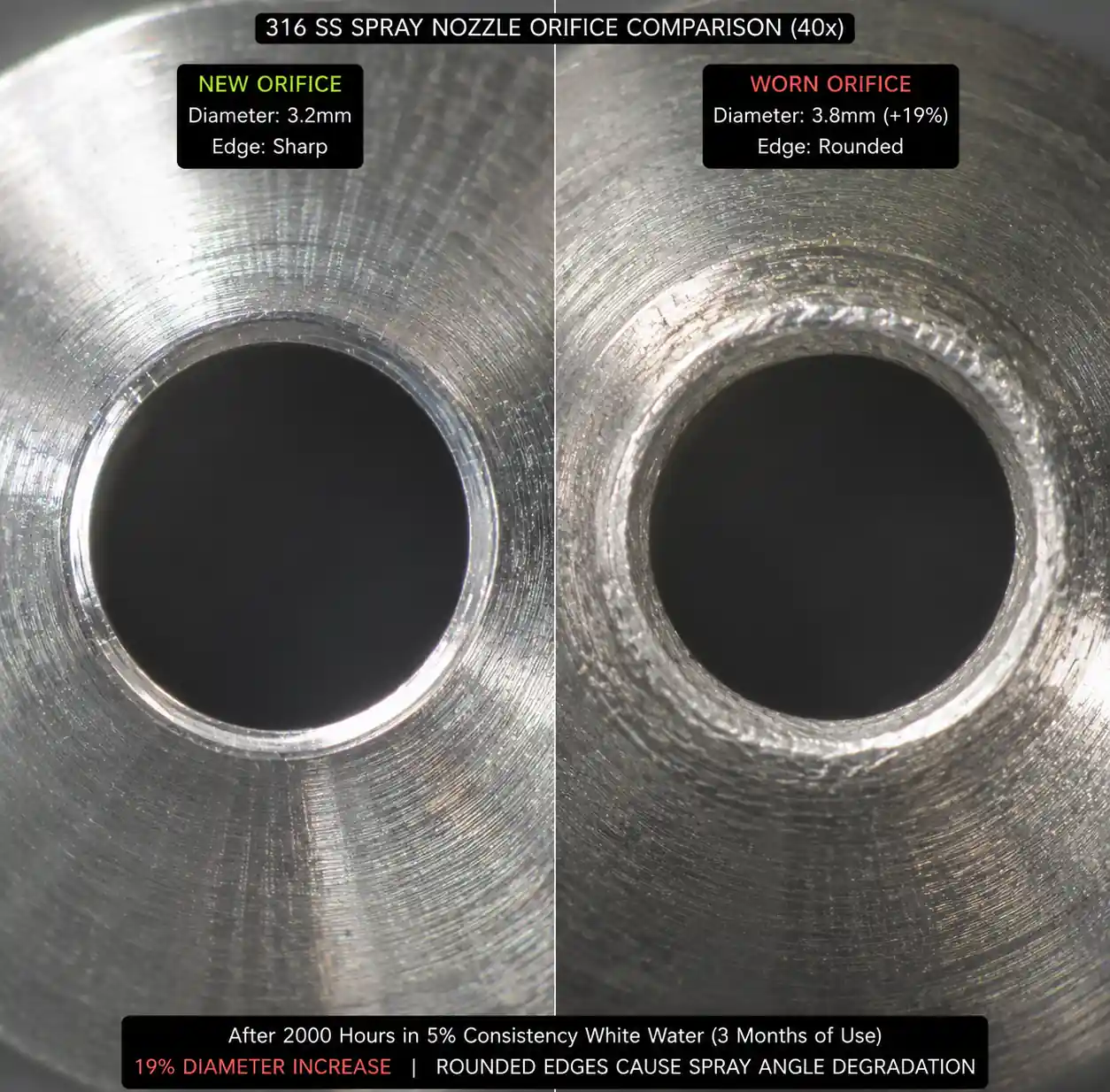
Nozzle wear in pulp washer service is primarily caused by erosion from suspended solids in recirculated white water (typically 3-8% consistency). The orifice gradually enlarges, increasing flow rate and reducing spray angle definition. From our accelerated wear testing, orifice diameter typically increases by 15-25% before the nozzle must be replaced.
Key wear factors:
- White water consistency and fiber coarseness
- Presence of bark fines, sand, and scale particles
- Operating pressure (wear rate approximately proportional to P^1.5)
- Nozzle material hardness and erosion resistance
5.2 Material Performance and Cost Comparison
Table 3: Nozzle Material Wear Life and Economics (White Water Service, 50 PSI, 5% Consistency)
| Material | Hardness (HV) | Relative Wear Life | Cost per Nozzle | Cost per Million Gallons | Best Application |
|---|---|---|---|---|---|
| 316 Stainless Steel | 170-220 | 1.0× (baseline: 2-4 months) | $12-18 | $54 | Clean white water, low-pressure pre-showers |
| Hardened 17-4 PH | 350-400 | 3.5-4.5× | $22-32 | $18 | General service, most vacuum drums |
| Tungsten Carbide | 1300-1500 | 18-25× | $85-125 | $6 | High-consistency, abrasive fiber (eucalyptus with bark) |
| Silicon Carbide (SiC) | 2400-2800 | 22-30× | $95-145 | $5 | Highest wear resistance, but brittle—avoid installations with water hammer risk |
| Alumina Ceramic (95-99%) | 1700-2000 | 12-18× | $55-85 | $8 | Good cost/performance balance for medium-wear applications |
Engineering recommendation: For most kraft pulp mill vacuum washers running on clean white water (under 6% consistency, low bark fines), we recommend hardened 17-4 PH stainless for the first trial. If replacement intervals fall below 6 months, upgrade to alumina ceramic or tungsten carbide in high-wear positions (first-stage showers see the most abrasive fiber).
5.3 Total Cost of Ownership Calculation Example
Consider a 3-stage vacuum drum washer with 120 total nozzles, operating 8000 hours per year:
Scenario A: 316 SS nozzles
- Nozzle life: 3 months (2000 hours)
- Replacements per year: 4 sets × 120 nozzles = 480 nozzles
- Annual nozzle cost: 480 × $15 = $7,200
- Labor (1 hour per shower change × 4 changes × $75/hr): $300
- Total annual cost: $7,500
Scenario B: Tungsten carbide nozzles
- Nozzle life: 20× longer = 60 months (replacement every 5 years)
- Replacements per year: 0.2 sets × 120 nozzles = 24 nozzles
- Annual nozzle cost: 24 × $105 = $2,520
- Labor: $60
- Total annual cost: $2,580
Savings: $4,920 per year (66% reduction), with payback in under 4 months.
This calculation doesn't even account for the secondary costs: downtime for nozzle replacement, flow imbalances from partially worn nozzles reducing wash efficiency, and increased fiber loss from spray pattern degradation.
6. Common Installation Mistakes and Field Fixes
6.1 Incorrect Standoff Distance
The problem: Nozzles installed too close (under 200 mm) or too far (over 400 mm) from drum surface.
Why it happens: Maintenance replaces a nozzle header during a shutdown without checking original design drawings. The new header gets welded in "approximately" the same position.
Impact: Too-close mounting creates excessive impact force that can dislodge fibers and erode the drum cover. Too-far mounting reduces impact force and creates wider, weaker spray patterns with poor penetration.
Field fix: Verify standoff distance with a measuring tape at 3 points across each header. Standard target is H = 8-12 inches (200-300 mm) for hydraulic fan nozzles at 40-60 PSI.
6.2 Misaligned Spray Angle
The problem: Nozzles rotated so spray fan is not perpendicular to drum axis—spray bands become diagonal, creating gaps.
Why it happens: Nozzles are threaded into headers without alignment pins. Thread tolerance allows ±30° rotation.
Impact: Can reduce effective coverage by 20-40%, creating unwashed streaks on the mat that show up as brightness or cleanliness variation in the final pulp.
Field fix: Install nozzles with alignment flats or use bodies with built-in orientation keys. After installation, verify spray alignment with a low-pressure water test (run drum at 10% speed, visually confirm spray bands are parallel to drum axis).
6.3 Unbalanced Flow Distribution
The problem: First nozzle in a header flows at design rate, but last nozzle only flows 60-70% of expected.
Why it happens: Undersized header pipe—velocity in the supply manifold creates pressure drop along the length.
Impact: Uneven wash water distribution across drum width, with end zones under-washed.
Field fix: Check header pipe diameter against rule of thumb: header ID should be at least 2× the total nozzle orifice area. For example, if you have 10 nozzles with 3.5 mm orifices each:
Total orifice area = 10 × π × (3.5 mm / 2)² = 96 mm²
Minimum header ID = 2√(96 mm²/π) ≈ 22 mm (about 1 inch)
If your header is smaller than this, you'll see significant pressure drop. Solution: increase header size or switch to center-feed manifold (supply enters at drum center, flows toward both edges).
6.4 Using the Wrong Thread Standard
The problem: Mixing NPT (tapered) and BSPP (parallel) threads when replacing nozzles.
Why it happens: Maintenance orders "equivalent" nozzles from a different supplier without checking thread specification.
Impact: Poor sealing, leaks, and potential safety hazard if nozzle blows out under pressure.
Field fix: Standardize on one thread type for your entire plant. In North America, 1/4" NPT is most common for pulp washer nozzles. In Europe and Asia-Pacific mills, 1/4" BSPP (G1/4) is standard. Document this in your spare parts database and physically label nozzle storage bins.
7. Troubleshooting Low Wash Efficiency
Table 4: Systematic Troubleshooting for Poor Wash Performance
| Symptom | Likely Root Cause | Diagnostic Test | Corrective Action |
|---|---|---|---|
| Displacement ratio dropping 5-10% over 3-6 months | Gradual nozzle wear, orifices enlarging | Measure flow from individual nozzles; compare to new nozzle spec | Replace nozzles when flow exceeds 115% of design |
| Sudden drop in wash efficiency after maintenance | Nozzles installed backward or misaligned | Visual inspection during low-speed test run | Reinstall with proper orientation |
| High wash efficiency on edges, poor in center 1/3 | Center nozzles clogged or header pressure drop | Check pressure gauges at header inlet and outlet; inspect nozzle orifices | Clean or replace clogged nozzles; verify header sizing |
| Washing good immediately after shower, but poor dilution at vat exit | Insufficient vat retention time (over-capacity) | Calculate actual retention time; check for short-circuiting | Reduce drum speed or increase vat level (if vacuum capacity allows) |
| Streaky washing pattern (alternating good/poor bands) | Missing nozzles or frozen spray (scale buildup) | Thermal imaging of shower headers (scale shows cooler) | Descale headers; consider filtration on white water supply |
| Fiber loss increasing with new high-pressure showers | Excessive impact force stripping mat | Reduce pressure from 80 to 50 PSI; measure white water consistency change | Optimize pressure to minimum needed for penetration |
Proactive monitoring recommendation: Install flow meters on each shower header and log data weekly. A gradual flow increase of 10-15% over several months indicates wear; a sudden jump suggests a nozzle failure or clog clearing. This early warning system typically pays for itself in under a year by catching problems before they significantly impact production.

8. FAQ
Q: Can I mix different spray angles in the same shower to optimize flow distribution?
A: Not recommended. While technically possible, mixing spray angles makes it nearly impossible to maintain consistent overlap and creates complex interaction patterns. Better approach: use uniform spray angles but vary nozzle flow rates (via orifice size) if you need differential application across the drum width.
Q: How often should nozzles be replaced in typical kraft mill service?
A: With hardened stainless (17-4 PH) nozzles: every 6-12 months. With ceramic or carbide: every 2-5 years. The key is to establish a flow monitoring program—replace when measured flow exceeds 115% of new nozzle specification, rather than waiting for a calendar interval.
Q: What's the best way to clean partially clogged nozzles?
A: Soak in warm (60-70°C) caustic solution (2-4% NaOH) for 30-60 minutes, then back-flush with clean water. Ultrasonic cleaning is even more effective for scale and fiber buildup. Never use metal tools to scrape orifices—this damages the precision edges and ruins spray pattern uniformity.
Q: Should shower water be filtered before the nozzles?
A: For nozzles with orifices below 2.0 mm, yes—use 60-80 mesh strainers (250-180 micron openings) on the supply line to each shower header. For typical pulp washer fan nozzles (2.5-4.0 mm orifices), filtration is optional but does extend nozzle life by 20-30% by removing large fiber clumps and debris.
Q: Can I increase wash water application rate by just cranking up the pressure?
A: Only to a limited extent. Remember Q = k√P, so increasing pressure from 50 to 80 PSI (1.6× pressure) only increases flow by 1.26×. Plus, higher pressure accelerates wear. If you need significantly more wash water, add nozzles or switch to higher-flow models.
Q: What causes spray angle to narrow as nozzles wear?
A: As the orifice erodes and becomes less sharply defined, the spray transitions from a clean flat fan to a more stream-like pattern. Once spray angle drops below 70% of original spec (e.g., an 80° nozzle producing 55° pattern), coverage gaps appear and wash efficiency drops noticeably. This is usually the trigger for replacement.
9. Conclusion and Next Actions
Optimizing fan-shaped nozzle arrangement in pulp washers is fundamentally an exercise in hydraulic geometry and material economics. The engineering keys are:
Design for 20-30% spray overlap to compensate for pattern edge taper and provide margin for wear-induced pattern changes.
Calculate total system flow requirements including drum rotation and multi-stage washing, not just a single header.
Select materials based on total cost of ownership, not initial purchase price—ceramic and carbide nozzles pay back in months through reduced replacement labor and improved wash consistency.
Monitor flow rates systematically to catch wear before it impacts production—a 15% flow increase is your early warning signal.
From the field data we've collected across dozens of installations, mills that implement proper nozzle spacing design and proactive wear monitoring consistently achieve 2-4% improvement in wash efficiency. At a typical 1000 ADMT/day mill, that translates to roughly $150,000-$300,000 per year in reduced bleaching chemical costs and improved pulp yield.