


Cold Rolling Emulsion Spraying: How Nozzle Selection Impacts Strip Shape Control
What You'll Learn: How hydraulic nozzle design, spray pattern uniformity, and flow characteristics directly affect thermal crown control, edge wave prevention, and flatness tolerance in cold rolling mills.
Table of Contents
- Introduction: Why Nozzle Selection Matters for Shape Control
- Critical Spray Parameters That Influence Strip Shape
- Nozzle Type Comparison for Cold Rolling Applications
- Flow Distribution and Thermal Crown Management
- Material Selection and Wear Impact on Shape Stability
- Installation Positioning and Maintenance Best Practices
- Troubleshooting Common Shape Control Issues
- FAQ
- Conclusion and Next Steps
1. Introduction: Why Nozzle Selection Matters for Shape Control
In modern cold rolling mills, maintaining strip flatness within ±10 I-units (flatness deviation) requires precise thermal management of work rolls. Emulsion spray cooling accounts for 60–75% of total heat removal during rolling, making nozzle selection one of the most critical—yet often overlooked—factors in shape control.
From our field experience working with tandem cold mills processing automotive-grade steel, we've observed that improper nozzle selection contributes to three persistent shape defects:
- Center buckle or edge wave caused by uneven coolant distribution across roll barrel width
- Quarter buckle resulting from insufficient flow density at intermediate zones
- Flatness instability during gauge transitions due to inconsistent thermal response
This guide addresses these issues by explaining how spray angle, droplet size, flow uniformity, and nozzle wear directly influence work roll thermal crown—and ultimately, strip shape. We'll provide selection criteria based on mill configuration, emulsion concentration, and flatness tolerance requirements.
What makes this different from generic nozzle guides: We focus specifically on the relationship between hydraulic spray characteristics and shape actuator effectiveness. You'll see worked examples of flow rate calculations, thermal crown modeling, and maintenance schedules derived from actual rolling mill data.
2. Critical Spray Parameters That Influence Strip Shape
Cold rolling shape control depends on managing work roll thermal expansion. The nozzle's job is to remove heat uniformly while allowing intentional thermal crown adjustments through variable coolant zones. Four spray parameters directly impact this:
2.1 Flow Rate and Pressure Relationship
Emulsion flow follows the standard hydraulic equation:
Q = K × √P
Where:
- Q = flow rate (L/min)
- K = nozzle flow coefficient (specific to orifice geometry)
- P = supply pressure (bar)
Critical insight for shape control: Doubling pressure increases flow by only 1.41×, not 2×. This non-linear relationship matters when compensating for worn nozzles or adjusting zone cooling intensity. In practice, we see many mills attempt to restore cooling capacity by increasing pressure, but this produces diminishing returns and accelerates wear.
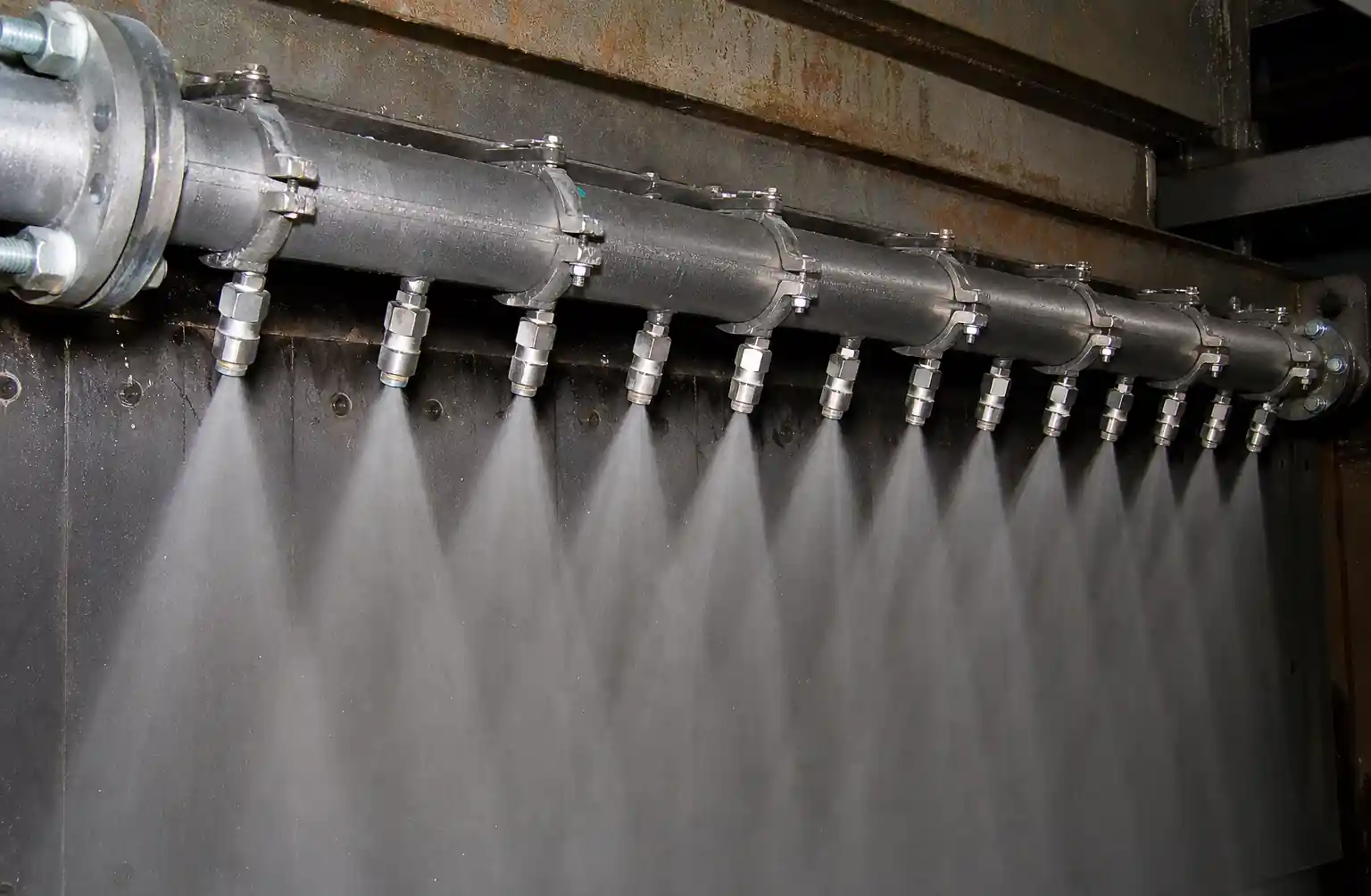
For a typical 6-high tandem mill work roll cooling system with 1,800mm barrel length:
- Each spray header requires 60–80 nozzles
- Target flow density: 15–25 L/min per meter of roll width
- Operating pressure range: 3–6 bar (higher pressure increases droplet impact but also misting losses)
2.2 Spray Angle and Coverage Uniformity
Spray angle determines overlap geometry between adjacent nozzles. For cold rolling emulsion systems:
- Narrow angles (40–60°): Better penetration through air barrier created by roll rotation, but require closer nozzle spacing
- Wide angles (80–110°): Easier coverage but more susceptible to deflection by air currents at high rolling speeds (>1,200 m/min)
Field data: At a automotive sheet mill running 1,400 m/min, switching from 110° to 65° flat fan nozzles reduced edge wave variation by 18% because narrower spray patterns penetrated the air boundary layer more effectively.
The overlap formula for uniform coverage:
Spacing = (2 × h × tan(α/2)) × 0.7
Where:
- h = nozzle-to-roll distance (typically 150–250mm)
- α = spray angle
- 0.7 = overlap factor (30% overlap prevents dry streaks)
2.3 Droplet Size Distribution
Droplet size affects heat transfer efficiency and emulsion oil carryover:
- Coarse droplets (300–600 μm): Higher impact force, better roll surface wetting, minimal mist generation—preferred for cold rolling
- Fine droplets (<200 μm): Higher surface area for heat transfer but prone to air entrainment and oil concentration drift
We measure droplet size distribution using laser diffraction (Malvern or Sympatec systems). The key metric is Dv50 (median droplet diameter).
Why this matters for shape: Fine misting causes uneven emulsion concentration across roll width because droplets evaporate before contact. This creates inconsistent heat transfer coefficients, leading to unpredictable thermal crown variations that flatness control models cannot compensate for.
Recommended Dv50 range for cold rolling emulsion (3–5% oil concentration): 250–450 μm
2.4 Impact Force and Roll Surface Wetting
Sufficient impact force is required to displace the air boundary layer rotating with the work roll. Insufficient impact leads to incomplete wetting and localized hot spots.
Impact force per nozzle can be estimated:
F ≈ ρ × Q × v
Where:
- ρ = emulsion density (~1,000 kg/m³)
- Q = volumetric flow rate (m³/s)
- v = jet velocity at impact point
At 5 bar spray pressure with 65° flat fan nozzles positioned 200mm from roll surface, typical impact force is 2–4 N per nozzle. This is sufficient for speeds up to 1,500 m/min.
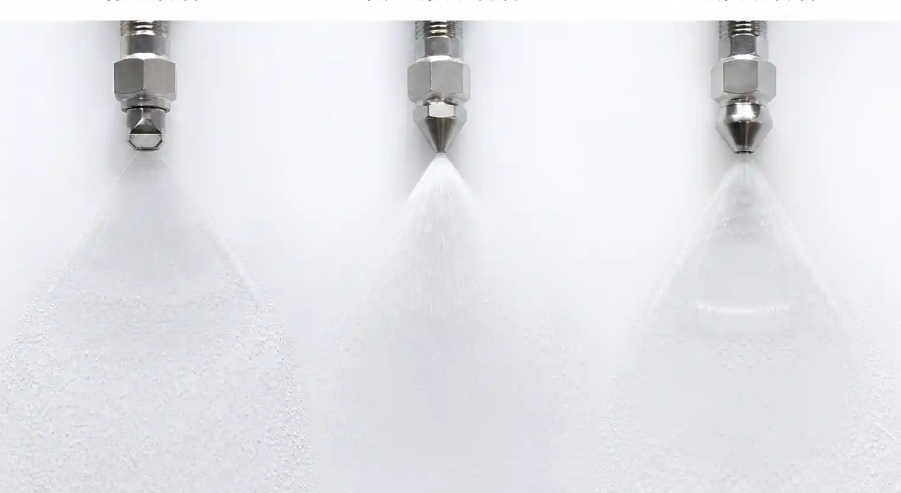
3. Nozzle Type Comparison for Cold Rolling Applications
Not all nozzle types suit cold rolling emulsion spraying. Here's a performance comparison based on mill field experience:
| Nozzle Type | Spray Pattern | Droplet Size Range (Dv50) | Flow Uniformity Across Width | Clogging Resistance | Suitability for Shape Control |
|---|---|---|---|---|---|
| Hydraulic Flat Fan | Elliptical plane | 250–500 μm | Excellent (±5% variation) | Good (if filtered to 100 μm) | Preferred – uniform coverage, predictable edge definition |
| Full Cone | Circular solid cone | 200–600 μm | Moderate (±12% variation) | Very good | Acceptable for non-critical zones; less uniform across roll width |
| Hollow Cone | Circular annular | 150–400 μm | Poor (±20% center/edge difference) | Good | Not recommended – doughnut pattern creates uneven thermal crown |
| Air Atomizing | Fine mist | 50–150 μm | Excellent | Moderate (dual-fluid complexity) | Avoid – excessive misting, oil concentration instability |
| Spiral Full Cone | Swirling solid cone | 300–700 μm | Good (±8% variation) | Excellent | Suitable for header zones with high contamination risk |
Recommendation: Hydraulic flat fan nozzles with 65–80° spray angle are the industry standard for work roll emulsion cooling because they provide:
- Uniform flow distribution across the roll barrel width
- Predictable spray edge boundaries for zone control
- Adequate droplet size to minimize misting
- Low maintenance complexity (single-fluid design)
Common mistake: Using full cone nozzles intended for tank washing applications. These produce circular spray patterns that create gaps or excessive overlap when arranged linearly along a roll face header, resulting in sinusoidal flow distribution that translates directly into thermal crown variation.
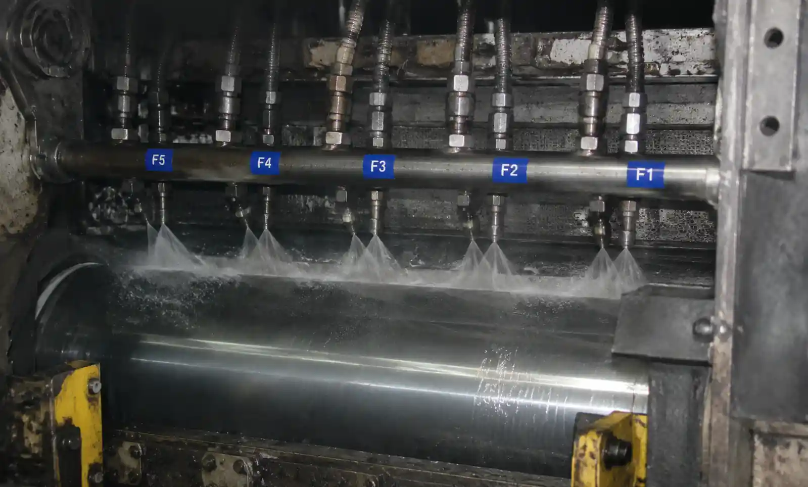
4. Flow Distribution and Thermal Crown Management
Work roll thermal crown development follows predictable patterns based on cooling distribution. Modern mills use multi-zone spray headers (typically 3–5 zones across roll width) to modulate thermal crown intentionally.
4.1 Thermal Crown Fundamentals
Work roll thermal expansion follows:
ΔD = α × D₀ × ΔT
Where:
- ΔD = diameter change
- α = thermal expansion coefficient (~11 × 10⁻⁶ /°C for steel)
- D₀ = original roll diameter
- ΔT = temperature rise
For a typical 600mm diameter work roll with 40°C average temperature rise during steady-state rolling:
ΔD = (11 × 10⁻⁶) × 600mm × 40°C = 0.264mm
This thermal crown must be counteracted or controlled by:
- Work roll bending (mechanical)
- Intermediate roll shifting (mechanical)
- Coolant zone flow modulation (thermal – where nozzle selection matters)
4.2 Nozzle Spacing and Zone Control Resolution
Zone cooling effectiveness depends on achieving distinct thermal boundaries between adjacent zones. This requires:
- Intra-zone uniformity: <±3% flow variation within each zone
- Inter-zone separation: Minimal spray overlap between zones (<10% of zone width)
Worked Example – 5-Zone Spray Header Design:
Mill configuration:
- Work roll barrel width: 1,600mm
- Zone distribution: Center zone (400mm) + 2 intermediate zones (300mm each) + 2 edge zones (300mm each)
- Target flow density: 20 L/min per meter
Selected nozzle: Flat fan 65°, K = 0.45 L/min/√bar
At 4 bar operating pressure:
- Flow per nozzle = 0.45 × √4 = 0.9 L/min
Nozzle spacing calculation:
- At 200mm standoff distance: Spacing = (2 × 200mm × tan(32.5°)) × 0.7 = 178mm
- Nozzles per meter = 1,000mm / 178mm ≈ 5.6 → use 6 nozzles/meter
- Actual flow density = 6 × 0.9 = 5.4 L/min per meter per header (×4 headers = 21.6 L/min total per meter) ✓
4.3 Flow Uniformity Measurement
We recommend quarterly flow distribution audits using catch-cup tests:
- Position collection trays at 100mm intervals across roll width
- Run spray system for 30 seconds at operating pressure
- Measure collected volume in each tray
- Calculate coefficient of variation (CV = standard deviation / mean)
Target performance:
- Within-zone CV: <5%
- Zone-to-zone intentional variation: controllable up to ±30%
Field observation: Mills running worn nozzles (>8,000 operating hours in abrasive emulsion) show CV increasing from 4% to 15%, causing unpredictable shape response to coolant zone adjustments.
5. Material Selection and Wear Impact on Shape Stability
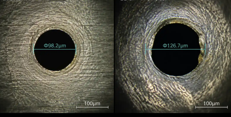
Nozzle wear in cold rolling emulsion systems is inevitable due to abrasive particles (mill scale fines, roll wear debris) in the recirculated coolant. Wear manifests as:
- Orifice enlargement → increased flow rate
- Spray angle narrowing → reduced coverage
- Asymmetric wear → skewed spray pattern
All three directly degrade shape control performance.
5.1 Material Performance Comparison
| Material | Hardness (HRC) | Relative Wear Life | Cost Multiple | Abrasion Resistance | Recommended Application |
|---|---|---|---|---|---|
| Hardened Stainless Steel (316) | 28–32 | 1× (baseline) | 1× | Moderate | Low-contamination emulsion, <3,000 hr intervals acceptable |
| Ceramic (Alumina 99%) | 85–88 | 8–12× | 4–6× | Excellent | Standard choice for work roll headers; balance of life and cost |
| Silicon Carbide | 90–95 | 15–20× | 8–12× | Superior | High-contamination environment or extended replacement intervals |
| Tungsten Carbide | 88–92 | 12–18× | 10–15× | Excellent | Good alternative to SiC but brittle under pressure spikes |
5.2 Wear Impact on Shape Control
Case study: A 5-stand tandem mill producing automotive exposed panels (0.7mm thickness, ±10 I-unit flatness tolerance) experienced increasing shape instability after 6,000 operating hours:
- Average nozzle orifice wear: +15% diameter increase
- Flow rate increase per nozzle: +23% (flow scales with orifice area, then adjusted by pressure drop changes)
- Within-zone flow CV: increased from 4.2% to 14.8%
- Shape control response: edge wave correction effectiveness reduced by 30%
Root cause: Uneven wear rates across nozzles (some wore 8%, others 22%) created flow distribution patterns that no longer matched the mill's thermal crown model assumptions.
Solution implemented:
- Switched from stainless steel to alumina ceramic nozzles (8× life)
- Established flow audit protocol every 2,000 hours
- Replaced entire zone when average wear exceeded +10% flow increase
Economic justification:
- Ceramic nozzles cost 5× more but last 8× longer
- Avoided shape-related downgrade from prime to commercial grade: $120/ton × 40 tons/day = $4,800/day
- Payback period: 3 weeks
5.3 Replacement Strategy
Two approaches:
Individual replacement: Replace nozzles when flow measurement exceeds +12% of nominal
- Pro: Lower upfront cost
- Con: Creates flow non-uniformity as new nozzles mix with worn ones
Zone replacement: Replace all nozzles in a zone simultaneously when average wear hits +10%
- Pro: Maintains within-zone uniformity
- Con: Higher replacement cost per event
Recommendation: Zone replacement for center and intermediate zones (critical for shape), individual replacement acceptable for edge zones.
6. Installation Positioning and Maintenance Best Practices
Proper nozzle installation directly affects spray performance. Common installation errors we've corrected:
6.1 Standoff Distance
Optimal range: 150–250mm from nozzle tip to roll surface
- Too close (<150mm): Spray pattern hasn't fully developed; risk of nozzle impact damage from roll vibration
- Too far (>300mm): Excessive droplet deceleration; air currents deflect spray pattern; increased misting
Measurement method: Use a depth gauge to verify standoff distance at three points across each header during installation and quarterly checks.
6.2 Spray Angle Alignment
Nozzles must be aligned:
- Axially: Spray fan perpendicular to roll axis (±2° tolerance)
- Radially: Spray centerline aimed at roll tangent point (not offset circumferentially)
Field observation: A 5° misalignment in axial positioning reduces effective coverage width by 12%, creating dry streaks that show up as localized hot bands and shape deviations.
6.3 Header Mounting Rigidity
Spray headers must be rigidly mounted to prevent vibration-induced positioning changes. We've seen mills where:
- Inadequate support brackets allowed 3–5mm header deflection under hydraulic pressure
- Vibration from mill operation caused gradual header rotation over months
- Result: Spray pattern gradually shifted, causing unexplained shape drift that operators compensated by retuning models—masking the root cause
Solution: Weld-mounted header brackets with vibration-damping bushings at 600mm intervals.
6.4 Filtration Requirements
Cold rolling emulsion systems recirculate coolant containing:
- Mill scale fines (10–100 μm)
- Roll wear debris (5–50 μm)
- Tramp oil and flocculants
Minimum filtration: 100 μm absolute for hydraulic flat fan nozzles with >0.8mm orifice diameter
Recommended filtration: 50 μm for optimal nozzle life; automatic backflushing filters to maintain flow pressure
6.5 Maintenance Schedule
| Task | Frequency | Acceptance Criteria |
|---|---|---|
| Visual inspection (clogging, physical damage) | Daily (operator check) | No visible debris, intact nozzle body |
| Flow distribution audit (catch-cup test) | Every 2,000 operating hours | Within-zone CV <8% |
| Individual nozzle flow measurement | Every 4,000 operating hours | <+12% deviation from nominal |
| Header alignment check | Every 6,000 hours or annual shutdown | Standoff distance 150–250mm, spray angle ±2° |
| Zone replacement | When average flow increase >+10% | Restore to nominal flow distribution |
7. Troubleshooting Common Shape Control Issues
7.1 Symptom: Edge Wave That Doesn't Respond to Coolant Zone Adjustment
Possible nozzle-related causes:
-
Uneven wear in edge zone nozzles
- Diagnosis: Measure flow from each edge nozzle; look for >15% variation
- Solution: Replace all edge zone nozzles simultaneously
-
Spray pattern deflection at high speed
- Diagnosis: Check if edge wave severity increases with rolling speed
- Solution: Switch to narrower spray angle nozzles (65° instead of 80°) or increase spray pressure to improve penetration
-
Insufficient coverage at strip edges
- Diagnosis: Water-sensitive paper test shows dry zones at edges
- Solution: Reduce nozzle spacing or add supplemental edge nozzles
7.2 Symptom: Center Buckle During Gauge Transitions
Possible nozzle-related causes:
-
Delayed thermal response in center zone
- Diagnosis: Center zone flow density significantly lower than intermediate zones
- Solution: Verify center zone nozzle count and flow rates; increase center zone pressure if needed
-
Misting causing inconsistent heat transfer
- Diagnosis: Visible mist cloud around work rolls; emulsion concentration drift
- Solution: Reduce spray pressure or switch to nozzles producing coarser droplets (increase orifice size)
7.3 Symptom: Flatness Variation Across Coil Length
Possible nozzle-related causes:
-
Intermittent nozzle clogging
- Diagnosis: Flow variation observed over time; improved filtration temporarily fixes issue
- Solution: Upgrade filtration to 50 μm; inspect for emulsion contamination sources
-
Temperature cycling in coolant supply
- Diagnosis: Spray pressure fluctuates; emulsion temperature varies ±5°C
- Solution: Not directly nozzle-related but affects spray performance; stabilize coolant system temperature
7.4 Diagnostic Flow Chart
Shape defect appears ↓ Has coolant zone tuning become less effective? ↓ Yes Perform flow distribution audit ↓ CV >8% within zone? ↓ Yes Measure individual nozzle flows ↓ Variation >15% between nozzles? ↓ Yes → Replace worn nozzles (zone replacement recommended) ↓ Still poor response? ↓ Check spray angle alignment and standoff distance ↓ Misalignment >3° or standoff out of range? ↓ Yes → Realign headers and verify with water-sensitive paper test

8. FAQ
Q: Can we mix different nozzle types within the same spray header?
A: Not recommended. Different nozzle types produce different spray patterns and droplet sizes, creating non-uniform cooling even if flow rates are matched. Stick with one nozzle type per header, preferably across all headers on a roll.
Q: How do we know when nozzle wear is affecting shape control versus other factors?
A: Perform a flow distribution audit. If within-zone coefficient of variation exceeds 8%, or if any nozzle flows >12% above nominal, nozzle wear is likely contributing. Also look for correlation between shape issues and operating hours since last nozzle replacement.
Q: Is higher spray pressure always better for heat removal?
A: No. While higher pressure increases flow slightly (remember the square root relationship), it also:
- Produces finer droplets more prone to misting
- Accelerates nozzle wear
- Can cause emulsion foaming Optimize for 3–6 bar; going beyond 8 bar rarely provides meaningful benefit for cold rolling applications.
Q: Should we use the same nozzles for work roll and backup roll cooling?
A: Not necessarily. Backup rolls have different thermal management requirements—they don't directly contact the strip and rotate slower. Many mills use wider-angle full cone nozzles for backup rolls since uniform coverage across width is less critical.
Q: How quickly does nozzle wear affect shape control?
A: It's gradual. In typical emulsion environments with moderate contamination:
- First 2,000 hours: Minimal impact, wear <5%
- 2,000–5,000 hours: Measurable wear (5–10%), shape control compensation still effective
- 5,000–8,000 hours: Significant wear (10–20%), reduced shape response, increased downgrade risk
-
8,000 hours: Severe wear (>20%), unpredictable shape behavior
The timeline compresses with higher contamination levels.
Q: Can we recover shape control performance without replacing nozzles?
A: Temporarily, by increasing spray pressure to compensate for flow loss, but this accelerates wear and creates other issues. The only permanent solution is nozzle replacement. Think of it like trying to compensate for worn mill bearings by increasing roll force—you can mask symptoms briefly but can't avoid the underlying mechanical problem.
9. Conclusion and Next Steps
Nozzle selection and maintenance directly impact cold rolling shape control through three mechanisms:
- Flow uniformity determines thermal crown predictability
- Spray pattern geometry affects zone cooling resolution
- Wear rate governs long-term shape control stability
The most important actions for maintaining shape control performance:
Immediate (if not already implemented):
- Verify current nozzle types match application requirements (hydraulic flat fan, 65–80° spray angle recommended)
- Perform flow distribution audit to establish baseline
- Check filtration adequacy (minimum 100 μm, preferably 50 μm)
Short-term (within 3 months):
- Implement quarterly flow audit schedule
- Establish nozzle replacement criteria (zone replacement when average wear >10%)
- Evaluate material upgrade to ceramic if currently using stainless steel
Long-term:
- Integrate nozzle performance tracking into shape control data systems
- Develop predictive replacement scheduling based on operating hours and contamination levels
- Consider automated flow monitoring systems for critical shape zones
Economic impact: Mills that implement systematic nozzle management see:
- 15–25% reduction in shape-related downgrades
- 30–40% longer nozzle service life (through proper material selection)
- 20–30% improvement in flatness consistency