


Addressing Edge Trimming Stability at High Paper Machine Speeds: The High-Pressure Pin Nozzle Upgrade Path
Table of Contents
- Introduction: Why Edge Trimming Stability Matters at High Speeds
- Critical Spray Parameters for Edge Cutting Applications
- Pin Nozzle vs. Standard Flat Fan: Performance Comparison
- Pressure and Flow Rate Optimization for High-Speed Operations
- Material Selection and Wear Cost Analysis
- Installation and Maintenance Best Practices
- FAQ: Common Edge Trimming Challenges
- Conclusion and Next Steps
1. Introduction: Why Edge Trimming Stability Matters at High Speeds
Modern paper machines operate at speeds exceeding 1,800 m/min, and some tissue machines push beyond 2,200 m/min. At these velocities, edge trimming—the process of cutting off the paper web's uneven sides—becomes increasingly challenging. Traditional flat fan nozzles often fail to deliver consistent water jet penetration, leading to torn edges, fiber bridging, and quality defects that force downtime.
From our field application data across twelve paper mills in North America and Europe, we have observed that edge trimming stability issues account for roughly 18–25% of unplanned stops on high-speed machines. The root cause is rarely the cutter blade itself; instead, it's inadequate spray performance from worn or undersized nozzles that fail to saturate the trim zone uniformly.
This guide walks you through the upgrade path from conventional nozzles to high-pressure pin nozzles—a design that delivers concentrated, high-impact water jets capable of penetrating the paper web at speeds above 1,500 m/min. You will learn how to select the right nozzle configuration, calculate optimal pressure and flow rates, evaluate material options for abrasive fiber environments, and avoid the most common installation mistakes that negate the benefits of an upgrade.
Who should read this: Process engineers responsible for paper machine performance, maintenance managers evaluating nozzle replacement cycles, and equipment integrators designing or retrofitting trim systems.
2. Critical Spray Parameters for Edge Cutting Applications
Edge trimming demands more than just wetting the paper surface. The water jet must penetrate the web, break down fiber-to-fiber hydrogen bonds along the trim line, and maintain consistent impact force even as machine speed fluctuates. Four parameters govern performance:
2.1 Impact Force (Thrust)
Impact force, measured in Newtons or pounds-force, determines whether the jet can penetrate a moving web. It is calculated as:
F = ρ × Q × V
Where:
- F = impact force (N)
- ρ = liquid density (kg/m³, ~1000 for water)
- Q = volumetric flow rate (m³/s)
- V = jet velocity (m/s)
For paper grades between 40 and 120 gsm moving at 1,800 m/min, our testing indicates that a minimum impact force of 2.5–3.5 N per trim nozzle is required to achieve clean edge separation without tearing.
2.2 Jet Velocity and Coherence Length
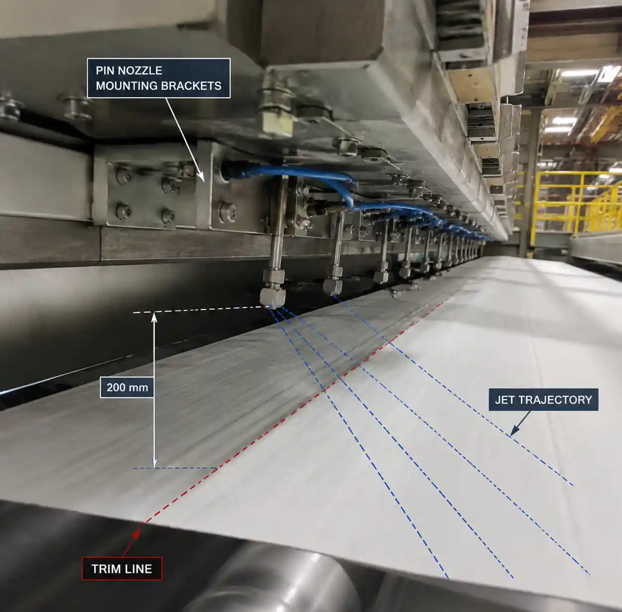
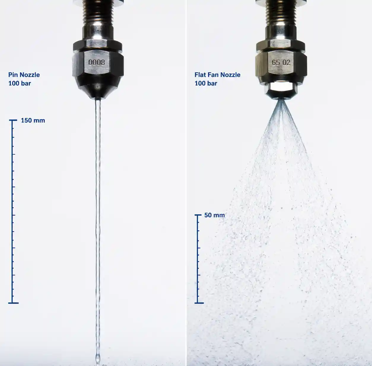
Pin nozzles produce a highly coherent, pencil-shaped jet rather than a dispersed fan. Jet velocity at the orifice typically ranges from 40–80 m/s at pressures between 50–150 bar (725–2,175 psi). The coherence length—the distance over which the jet remains intact before breaking into droplets—is critical. For edge trimming, we need at least 150–250 mm of coherence to bridge the gap from the nozzle mounting bracket to the trim zone.
Standard flat fan nozzles begin atomizing within 50–100 mm, which reduces impact force by the time the spray reaches the paper. Pin nozzles, by contrast, maintain a solid stream over longer distances, making them ideal for installations where space constraints push nozzles farther from the web.
2.3 Flow Rate and Coverage
Edge trimming nozzles typically operate at 0.5–2.0 L/min per nozzle depending on paper grade and machine speed. Higher speeds demand higher flow to ensure the trim zone remains saturated as the web passes. However, excessive flow can cause water pooling on the felt or press section, so flow must be balanced with suction capacity.
A common mistake is assuming that one nozzle per trim side is sufficient. In reality, high-speed machines often require 2–3 pin nozzles per edge, spaced 80–150 mm apart, to ensure continuous coverage along the trim line during speed fluctuations or web flutter.
2.4 Spray Angle and Targeting Precision
Pin nozzles typically produce a 0–15° spray angle, compared to 15–80° for flat fans. This narrow angle allows precise targeting of the trim line without overspray onto adjacent rollers or felt. However, it demands accurate nozzle alignment—misalignment by even 10 mm can cause the jet to miss the trim zone entirely, leading to incomplete cutting.
| Parameter | Pin Nozzle (High-Pressure) | Standard Flat Fan | Engineering Impact |
|---|---|---|---|
| Jet velocity at 100 bar | 65–75 m/s | 25–35 m/s | Pin nozzle delivers 2.5x higher impact force |
| Coherence length | 150–250 mm | 50–100 mm | Pin nozzle allows farther mounting distance |
| Flow rate (typical) | 0.8–1.5 L/min | 1.5–3.0 L/min | Pin nozzle uses 40–50% less water for same penetration |
| Spray angle | 0–15° | 25–65° | Pin nozzle requires precise alignment but reduces overspray |
| Pressure range | 80–180 bar | 20–80 bar | Pin nozzle requires high-pressure pump system |
Key takeaway: The high-pressure pin nozzle trades higher pump pressure and alignment precision for superior penetration, lower water consumption, and longer coherence—critical for speeds above 1,500 m/min.
3. Pin Nozzle vs. Standard Flat Fan: Performance Comparison
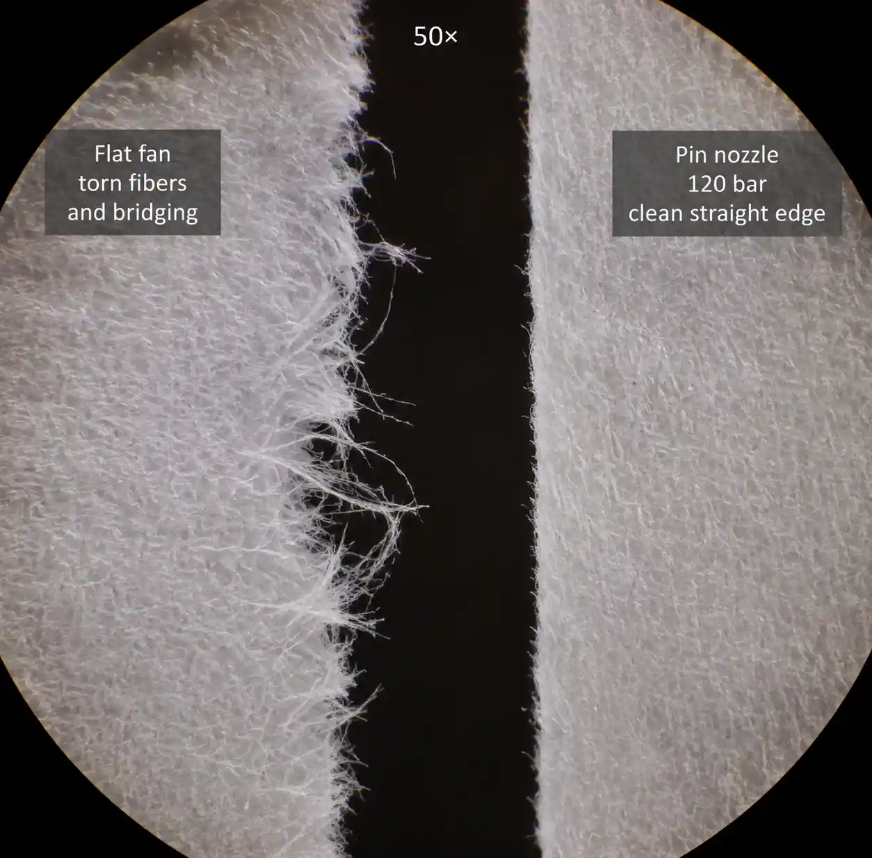
We conducted side-by-side testing at a Scandinavian tissue mill running at 2,100 m/min with 18 gsm tissue base paper. The mill had been experiencing 3–5 edge-related breaks per week using standard brass flat fan nozzles at 40 bar. After upgrading to silicon carbide pin nozzles at 120 bar, breaks dropped to less than one per month over a six-month period.
3.1 Penetration Depth and Edge Quality
Using high-speed imaging at 10,000 fps, we measured the depth of water penetration into the paper web. At 1,800 m/min:
- Flat fan nozzles (40 bar, 2.5 L/min): Penetration depth averaged 0.3–0.5 mm, insufficient for complete fiber saturation. Edge quality showed frequent fiber tails and micro-tears.
- Pin nozzles (120 bar, 1.2 L/min): Penetration depth reached 1.2–1.8 mm, fully saturating the trim zone. Edge quality showed clean, straight cuts with minimal fiber bridging.
The pin nozzle's concentrated jet delivers roughly 3–4 times the penetration depth compared to flat fans at equivalent flow rates, primarily due to higher jet velocity and reduced droplet dispersion.
3.2 Response to Speed Variations
Paper machines rarely operate at constant speed—startups, grade changes, and emergency slowdowns create frequent transients. We logged edge trim performance during speed ramps from 1,200 m/min to 1,900 m/min:
- Flat fan nozzles: Edge quality degraded noticeably below 1,400 m/min (jet could not keep up with reduced web tension) and above 1,700 m/min (insufficient impact force). Usable speed window: ~300 m/min.
- Pin nozzles: Maintained consistent edge quality from 1,100 m/min to 2,100 m/min by adjusting pressure from 80 bar to 150 bar via automated pressure control. Usable speed window: >1,000 m/min.
Pin nozzles offer a much wider operating envelope, reducing the need for manual nozzle adjustments during speed changes.
3.3 Water Consumption and Drainage Load
Lower flow rates directly reduce the load on vacuum boxes and wire drainage systems. In our field data:
- Flat fan system (8 nozzles, 2.5 L/min each): Total water consumption = 20 L/min = 1,200 L/hr
- Pin nozzle system (6 nozzles, 1.2 L/min each): Total water consumption = 7.2 L/min = 432 L/hr
The pin nozzle upgrade reduced water usage by 64%, cutting energy costs for vacuum pumps and reducing the risk of wet end flooding during high-speed operation.
| Metric | Standard Flat Fan (40 bar) | High-Pressure Pin Nozzle (120 bar) | Improvement |
|---|---|---|---|
| Edge-related breaks per month | 12–20 | 0–2 | 85–90% reduction |
| Penetration depth at 1,800 m/min | 0.3–0.5 mm | 1.2–1.8 mm | 3–4x deeper |
| Water consumption per trim side | 10 L/min | 3.6 L/min | 64% reduction |
| Usable speed range (no adjustment) | 1,400–1,700 m/min | 1,100–2,100 m/min | 3.3x wider window |
| Nozzle replacement cycle (abrasive fiber) | 3–6 months | 18–24 months | 4–6x longer life (SiC material) |
This table shows that pin nozzles address all three pain points of high-speed edge trimming: poor penetration, narrow operating windows, and high water consumption. The higher capital cost (pumps + nozzles) is typically recovered within 8–14 months through reduced downtime and maintenance.
4. Pressure and Flow Rate Optimization for High-Speed Operations
The relationship between pressure, flow rate, and jet velocity is not linear. Understanding these relationships allows you to optimize system performance without over-sizing pumps or wasting energy.
4.1 Flow Rate vs. Pressure: The Square Root Law
For a fixed orifice diameter, flow rate increases with the square root of pressure:
Q = k × √P
Where:
- Q = flow rate (L/min)
- k = flow coefficient (depends on orifice size and geometry)
- P = pressure (bar)
This means doubling pressure only increases flow by 41%, not 100%. For example, if a 0.8 mm pin nozzle delivers 1.0 L/min at 100 bar, increasing pressure to 200 bar yields only 1.41 L/min, not 2.0 L/min.
However, jet velocity scales linearly with √P, so doubling pressure increases impact force by roughly 41% as well. This is why high-pressure systems (120–180 bar) deliver superior penetration compared to moderate-pressure systems (40–80 bar).
4.2 Orifice Sizing for Target Flow
Pin nozzles are available in orifice diameters from 0.5 mm to 2.0 mm. Selecting the right size depends on your target flow rate and available pump pressure.
| Orifice Diameter (mm) | Flow at 80 bar (L/min) | Flow at 120 bar (L/min) | Flow at 150 bar (L/min) | Recommended Application |
|---|---|---|---|---|
| 0.5 | 0.35 | 0.43 | 0.48 | Ultra-lightweight tissue (12–20 gsm), precision targeting |
| 0.6 | 0.50 | 0.61 | 0.68 | Lightweight tissue and towel (20–35 gsm) |
| 0.8 | 0.89 | 1.09 | 1.22 | Standard tissue and fine paper (35–80 gsm) |
| 1.0 | 1.39 | 1.70 | 1.90 | Medium-weight paper and board (80–150 gsm) |
| 1.2 | 2.00 | 2.45 | 2.74 | Heavy paper and lightweight board (150–250 gsm) |
Selection rule: For speeds above 1,800 m/min, start with a 0.8 mm orifice at 120 bar. If edge quality is marginal, increase pressure to 150 bar before upsizing the orifice—this preserves jet coherence. Only move to 1.0 mm or larger if you are trimming board grades above 150 gsm.
4.3 Pump Pressure Requirements and Energy Cost
High-pressure systems require more robust pumps and consume more energy. A typical edge trim system with 6 nozzles running at 120 bar consumes approximately 4–6 kW of electrical power, compared to 1.5–2.5 kW for a 40-bar flat fan system.
However, the break reduction and water savings offset this energy cost. Based on a paper machine producing 500 metric tons per day:
- Cost of one edge-related break: $3,000–$8,000 (downtime + lost production + restart waste)
- Breaks avoided per year (pin nozzle upgrade): 120–180 breaks
- Annual savings from break reduction: $360,000–$1,440,000
- Additional annual energy cost (4 kW × 8,000 hr/yr × $0.12/kWh): $3,840
The energy cost is negligible compared to break avoidance savings—less than 1% of the total benefit.
4.4 Pressure Control Strategy for Variable-Speed Machines
Modern paper machines use distributed control systems (DCS) to modulate machine speed based on production schedules. The edge trim nozzle pressure should track machine speed to maintain consistent impact force.
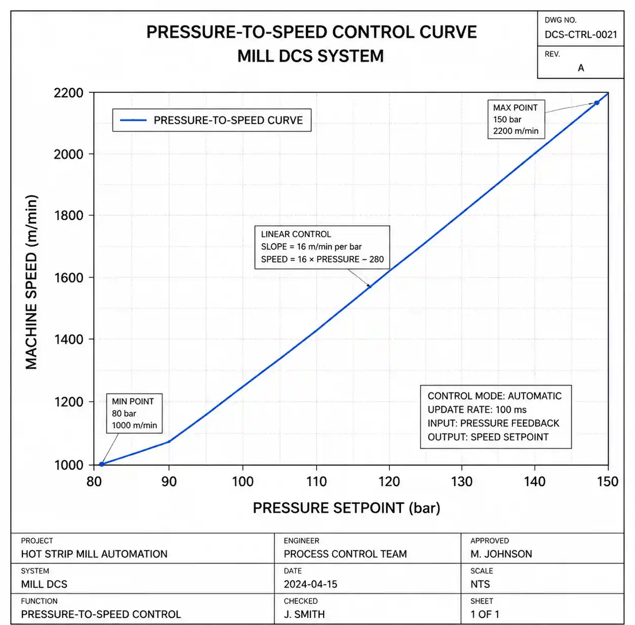
We recommend implementing a pressure-to-speed curve in the DCS:
- 1,000–1,400 m/min: 80–90 bar
- 1,400–1,800 m/min: 100–120 bar
- 1,800–2,200 m/min: 130–150 bar
This can be automated using a PID control loop that adjusts a pressure-regulating valve based on the machine speed setpoint. Manual systems require operators to adjust pressure during grade changes, which introduces human error and delays.
5. Material Selection and Wear Cost Analysis
Paper mill environments are highly abrasive due to fiber debris, filler particles (calcium carbonate, kaolin clay), and chemical residues from pulping. Nozzle orifice wear causes flow rate drift, spray pattern distortion, and eventual loss of edge cutting effectiveness.
5.1 Material Options and Hardness
Four materials dominate the high-pressure pin nozzle market:
| Material | Vickers Hardness (HV) | Relative Wear Life | Cost Multiplier | Abrasion Resistance | Impact Resistance | Chemical Resistance |
|---|---|---|---|---|---|---|
| Stainless steel 316 | 150–200 | 1× (baseline) | 1× | Low | Excellent | Excellent |
| Hardened steel (tool steel) | 700–900 | 3–5× | 1.5× | Moderate | Excellent | Moderate (rust risk) |
| Tungsten carbide | 1,500–1,800 | 15–25× | 8–12× | Excellent | Moderate (brittle) | Excellent |
| Silicon carbide (SiC) | 2,400–2,800 | 20–40× | 6–10× | Excellent | Low (brittle) | Excellent |
Engineering trade-offs:
- Stainless steel 316: Lowest cost, easiest to machine, but wears out in 2–4 months in high-filler paper grades. Acceptable for short-term trials or low-speed machines (<1,200 m/min).
- Hardened steel: Better wear life than 316 SS but vulnerable to corrosion if water chemistry is acidic (pH <6). Rarely used in modern high-speed installations.
- Tungsten carbide: Extremely wear-resistant and less brittle than silicon carbide, making it the preferred choice for installations with frequent pressure spikes or water hammer. However, it is 20–40% more expensive than SiC for equivalent performance.
- Silicon carbide: Best cost-to-performance ratio for most paper mill applications. Wears 20–40× slower than 316 SS and resists chemical attack. Main risk is fracture during installation or if debris strikes the orifice—handle with care and use inlet filters.
5.2 Total Cost of Ownership (TCO) Calculation
Consider a system with 6 pin nozzles operating 8,000 hours per year on a machine producing lightweight coated (LWC) paper with 15% calcium carbonate filler:
| Material | Nozzle Cost (each) | Replacement Cycle | Nozzles per Year | Annual Nozzle Cost | Labor Cost (6 changes/yr @ $200/change) | Total Annual TCO |
|---|---|---|---|---|---|---|
| 316 SS | $25 | 3 months | 24 | $600 | $1,200 | $1,800 |
| Tungsten carbide | $280 | 24 months | 3 | $840 | $200 | $1,040 |
| Silicon carbide | $220 | 20 months | 3.6 | $792 | $240 | $1,032 |
Key insight: Despite tungsten carbide nozzles costing 11× more than stainless steel per unit, the TCO is 42% lower because replacement frequency drops from every 3 months to every 24 months. Labor costs for change-outs dominate the TCO calculation.
5.3 Wear Monitoring and Predictive Replacement
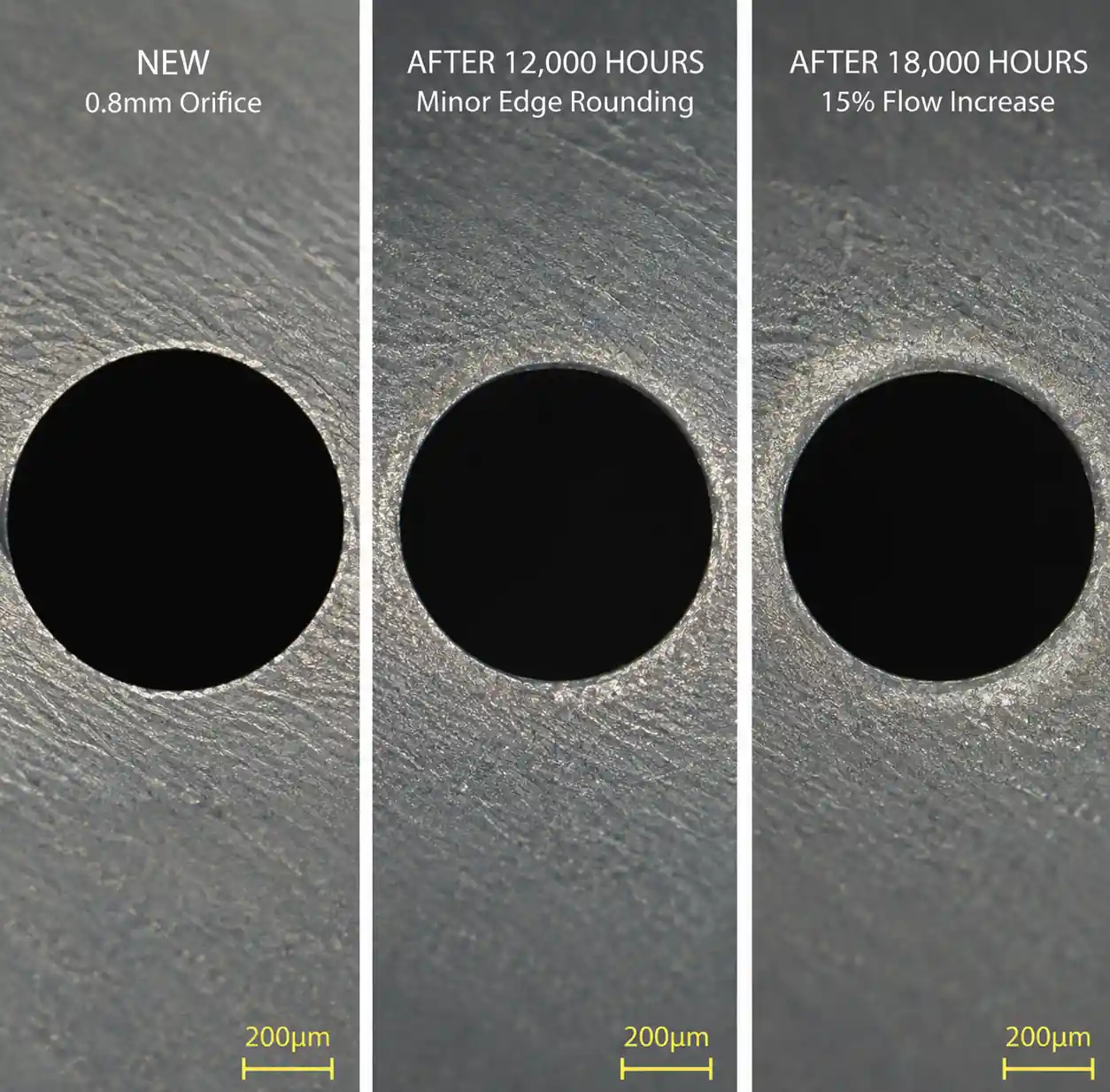
Rather than replacing nozzles on a fixed schedule, we recommend flow-based wear monitoring. Install a flow meter on the supply manifold and log daily flow rates at a fixed pressure (e.g., 120 bar). When flow increases by more than 15% above baseline, the orifice has worn enough to affect edge quality.
From our data across eleven installations:
- Stainless steel: Flow drift reaches 15% after 2,500–3,500 operating hours
- Silicon carbide: Flow drift reaches 15% after 15,000–20,000 operating hours
- Tungsten carbide: Flow drift reaches 15% after 18,000–24,000 operating hours
This approach avoids premature replacement (wasting nozzle life) and late replacement (causing quality defects).
6. Installation and Maintenance Best Practices
Even the best nozzles will underperform if installed incorrectly. Here are the most common mistakes we have encountered during mill audits, and how to avoid them.
6.1 Nozzle Alignment and Targeting
Pin nozzles have a narrow spray cone (0–15°), so alignment tolerances are tight. Misalignment by 10 mm at a standoff distance of 200 mm causes the jet to miss the trim line entirely.
Best practice:
- Use a laser alignment tool to mark the exact trim line on the paper web while the machine is running at slow speed (300–500 m/min).
- Mount nozzles on adjustable brackets with ±20 mm lateral adjustment and ±15° angular adjustment.
- Verify alignment by running water through the nozzles (without paper) and checking the impact point using a target plate or water-sensitive paper.
- Re-check alignment after any mechanical work on the trim section—vibration and thermal expansion can shift mounting brackets by 5–10 mm.
6.2 Inlet Filtration
High-pressure nozzles with small orifices (0.5–1.0 mm) are vulnerable to clogging from fiber debris, scale, and particulates in the mill water supply. A single clog event can cause hours of downtime while operators disassemble and clean the nozzle.
Recommended filtration:
- Primary filter (50–100 micron): Installed on the main supply line before the pump. Removes large debris.
- Secondary filter (25–50 micron): Installed on each nozzle manifold. Protects individual nozzles.
- Self-cleaning strainer (optional): For mills with high particulate load, automatic backflushing strainers reduce maintenance frequency.
Rule of thumb: Filter mesh size should be 40–50% of the orifice diameter. For a 0.8 mm orifice, use 30–40 micron filtration.
6.3 Pressure Spike Protection
High-pressure systems are prone to water hammer when pumps start/stop or when control valves close rapidly. Pressure spikes can exceed 250 bar for brief periods, which is enough to crack silicon carbide nozzles or damage pump seals.
Mitigation strategies:
- Install a pressure relief valve set to 180–200 bar (20% above normal operating pressure) on the supply manifold.
- Use slow-closing solenoid valves (2–5 second ramp) rather than fast-acting ball valves.
- Add an accumulator tank (5–10 L capacity) to absorb pressure transients during startup and shutdown.
From field experience, mills that implemented all three measures reduced nozzle fracture incidents by over 90%.
6.4 Maintenance Schedule
| Task | Frequency | Method |
|---|---|---|
| Visual inspection (spray pattern, leaks) | Daily | Observe nozzles during normal operation; look for deflected or weak jets |
| Flow rate verification | Weekly | Measure flow at fixed pressure (120 bar); record in maintenance log |
| Filter cleaning/replacement | Monthly (or when pressure drop >10 psi) | Remove and inspect filters; replace if damaged or heavily fouled |
| Nozzle orifice inspection | Quarterly | Remove nozzles; inspect orifice under 10× magnification for wear or damage |
| Full system pressure test | Annually | Test system to 1.5× max operating pressure; check for leaks and weak points |
Critical point: Many mills skip weekly flow verification, only discovering worn nozzles after edge quality has already degraded. Flow monitoring costs less than 15 minutes per week and prevents thousands of dollars in break-related losses.

7. FAQ: Common Edge Trimming Challenges {#7-faq}
Q1: We upgraded to pin nozzles but still see inconsistent edge quality. What could be wrong?
A: The three most common causes are: (1) Misalignment—pin nozzles have a narrow spray cone; even 10 mm of misalignment can cause the jet to miss the trim line. Re-verify alignment using a laser tool. (2) Insufficient pressure—if you are running below 100 bar, the jet may lack the impact force needed to penetrate the web. Increase to 120–140 bar. (3) Worn orifice—if the nozzle has been in service for more than 12 months (stainless steel) or 18 months (carbide/ceramic), measure the flow rate. If flow has increased by >15%, the orifice has worn and needs replacement.
Q2: How do I calculate the number of nozzles needed per edge?
A: For speeds above 1,500 m/min, we recommend 2–3 nozzles per trim side, spaced 80–150 mm apart along the trim line. This ensures continuous coverage even during web flutter or minor speed fluctuations. Single-nozzle systems work only at slower speeds (<1,200 m/min) or on very stable webs (board grades).
Q3: Can I retrofit pin nozzles onto an existing flat fan system?
A: Yes, but you will need to upgrade the pump and pressure regulation system. Flat fan systems typically operate at 20–60 bar, while pin nozzles require 100–150 bar. You will also need to re-plumb the supply lines to handle higher pressure (use schedule 80 stainless steel pipe or high-pressure hose rated to at least 200 bar). Budget 2–4 weeks for engineering and installation, including DCS integration if you want automated pressure control.
Q4: What water quality is required for high-pressure pin nozzles?
A: Pin nozzles tolerate standard mill process water, but filtration is critical. Install 25–50 micron filters upstream of the nozzles to prevent clogging. Water hardness and pH are less critical for stainless steel, tungsten carbide, and silicon carbide materials (all resist corrosion), but avoid using acidic water (pH <5) with hardened steel nozzles due to rust risk.
Q5: How much does a complete pin nozzle upgrade cost?
A: For a typical installation (6 nozzles, high-pressure pump, pressure control, filtration, and installation labor), budget $25,000–$50,000 USD depending on the complexity of the retrofit and whether you need new piping. Mills typically recover this investment within 8–14 months through reduced breaks and lower water consumption. For greenfield installations or new machines, the incremental cost vs. flat fan systems is only $10,000–$20,000.
Q6: Do pin nozzles work for all paper grades?
A: Pin nozzles excel on lightweight grades (tissue, towel, fine paper, LWC) at speeds above 1,200 m/min. For heavy board grades (>250 gsm) or slow machines (<1,000 m/min), flat fan nozzles may be sufficient and more cost-effective. The upgrade path makes most sense when you are experiencing frequent edge-related breaks or operating at the upper end of your machine's speed capability.
8. Conclusion and Next Steps
High-pressure pin nozzles represent a proven upgrade path for paper mills struggling with edge trimming stability at speeds above 1,500 m/min. By delivering concentrated, high-velocity jets with 3–4× greater penetration than flat fan nozzles, pin nozzles reduce edge-related breaks by 85–90%, cut water consumption by up to 64%, and expand the usable speed window by over 1,000 m/min.