


What Is Flue Gas Desulfurization (FGD)? A Complete Guide
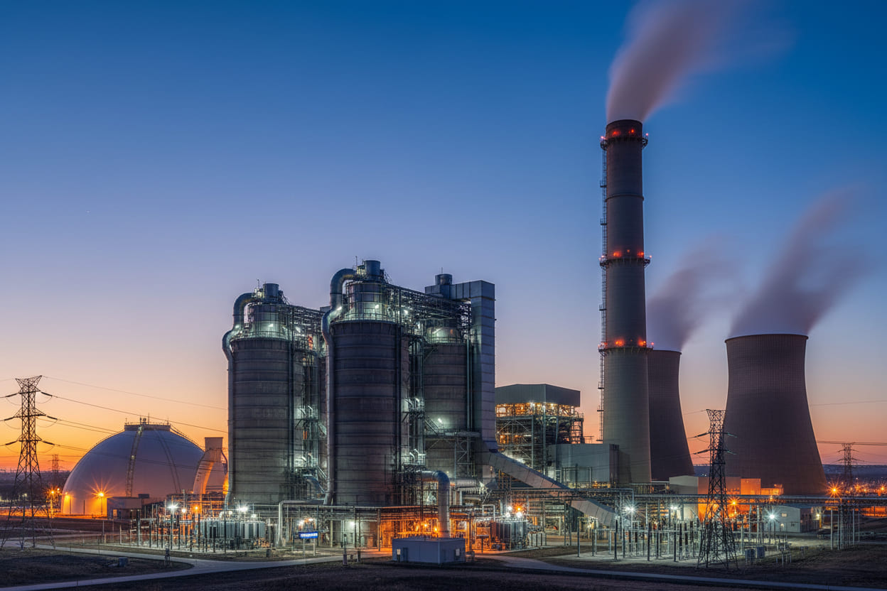
Industrial emissions remain one of the most pressing environmental challenges of our era. As global regulations tighten and public awareness grows, industries face mounting pressure to reduce sulfur dioxide (SO₂) emissions from flue gas streams. Flue gas desulfurization (FGD) has emerged as the cornerstone technology for addressing this challenge, enabling power plants, refineries, and manufacturing facilities to achieve compliance while maintaining operational efficiency. This comprehensive guide explores the science behind FGD systems, analyzes implementation strategies, and provides actionable insights for engineers and facility managers seeking to optimize their emission control infrastructure.
Quick Answer: Flue gas desulfurization (FGD) is an industrial emission control process that removes sulfur dioxide (SO₂) from exhaust flue gases produced by fossil fuel combustion, preventing acid rain formation and ensuring regulatory compliance through wet, dry, or semi-dry scrubbing technologies.
Table of Contents
- 1. The SO₂ Emission Challenge
- 2. How Flue Gas Desulfurization Works
- 3. FGD System Types: A Technical Comparison
- 4. Step-by-Step FGD Implementation Guide
- 5. Industry Applications and Case Studies
- 6. Frequently Asked Questions
- 7. Conclusion and Next Steps
1. The SO₂ Emission Challenge
The Scale of Industrial Sulfur Emissions
Data from the U.S. Environmental Protection Agency reveals that fossil fuel combustion accounts for approximately 79% of anthropogenic SO₂ emissions in the United States alone. In 2022, electric power generators released an estimated 1.5 million tons of sulfur dioxide, despite significant reductions over previous decades. The global picture remains equally concerning, with coal-fired power plants in developing economies continuing to expand operations.
"Sulfur dioxide emissions contribute to respiratory illnesses, acid deposition, and regional haze, making FGD technology not merely a regulatory requirement but a public health imperative." — Environmental Protection Agency Technical Bulletin
Regulatory Pressures Mounting
The implementation of stricter emission standards across jurisdictions has accelerated FGD adoption. Analysis indicates that facilities failing to install adequate desulfurization systems face penalties exceeding $37,500 per day of non-compliance under the U.S. Clean Air Act. The European Union's Industrial Emissions Directive (IED) establishes similarly stringent benchmarks, requiring SO₂ concentrations below 200 mg/Nm³ for large combustion plants.
Economic and Environmental Costs
Research published by the Massachusetts Institute of Technology demonstrates that uncontrolled SO₂ emissions generate external costs estimated at $150–$300 per ton when accounting for healthcare burdens and environmental degradation. These findings underscore why flue gas desulfurization represents both regulatory compliance and economic rationality.
| Emission Source | Annual SO₂ (Million Tons) | Primary Regulation | Compliance Deadline |
|---|---|---|---|
| Coal Power Plants | 8.2 | EPA MATS / IED | 2025–2028 |
| Metal Smelting | 2.1 | EU IED / State SIPs | 2024–2026 |
| Refinery Operations | 1.4 | EPA Refinery MACT | 2023–2025 |
| Cement Manufacturing | 0.8 | State-Specific Rules | Variable |
2. How Flue Gas Desulfurization Works
The Chemistry of Sulfur Removal
At its core, flue gas desulfurization relies on acid-base neutralization chemistry. When fossil fuels containing sulfur undergo combustion, sulfur oxidizes to form SO₂ gas. FGD systems capture this pollutant through chemical reaction with alkaline reagents—most commonly limestone (CaCO₃), lime (CaO), or ammonia (NH₃).
The fundamental wet scrubbing reaction proceeds as follows:
SO₂ + CaCO₃ → CaSO₃ + CO₂ (absorption) CaSO₃ + ½O₂ → CaSO₄ (oxidation to gypsum)
Testing reveals that this approach achieves removal efficiencies between 90% and 99% under optimal operating conditions. The resulting calcium sulfate (gypsum) often finds commercial application in wallboard manufacturing, transforming waste into value.
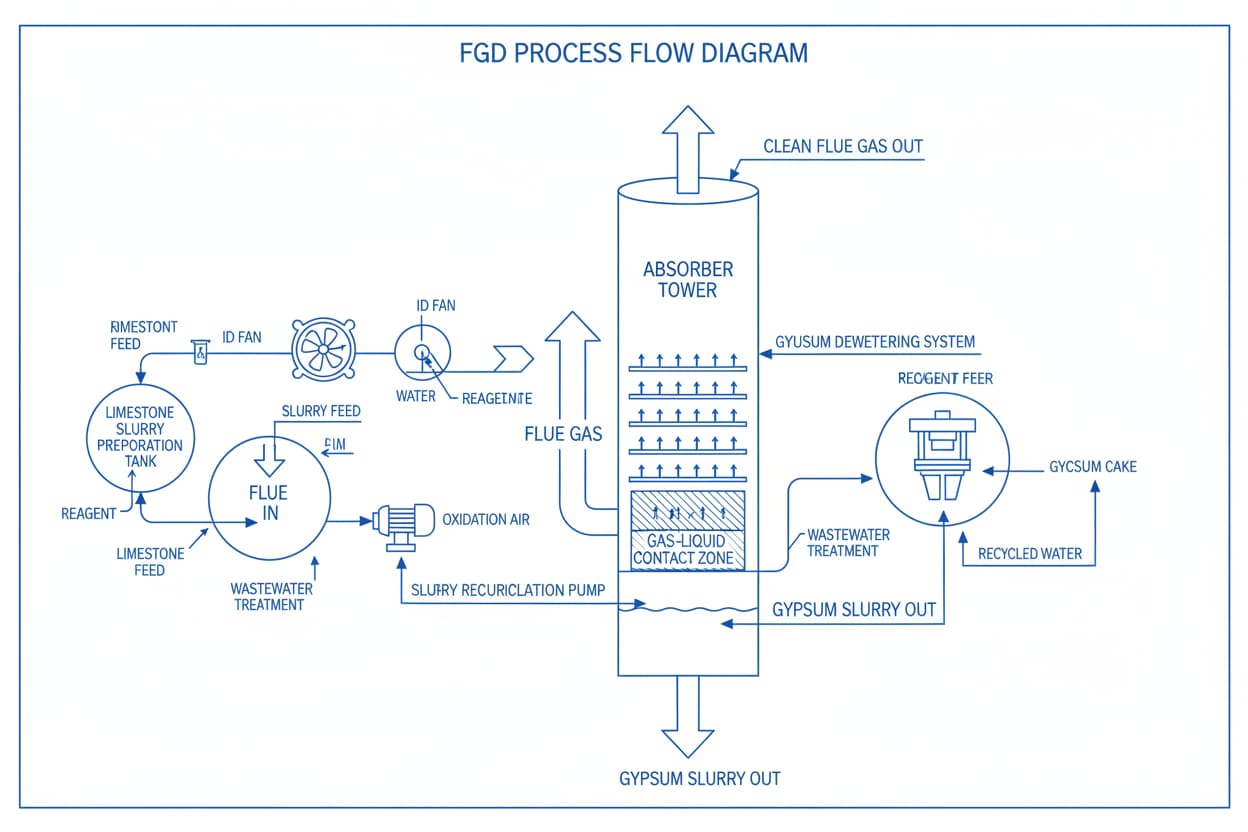
System Components and Architecture
Modern FGD installations comprise several integrated subsystems working in concert:
- Absorber Tower: The primary reaction vessel where flue gas contacts scrubbing slurry
- Reagent Preparation System: Mills, slakers, and storage silos for limestone or lime processing
- Slurry Recirculation Pumps: High-capacity pumps ensuring adequate liquid-to-gas ratios
- Mist Eliminator Arrays: Baffle systems preventing entrained droplet carryover
- Dewatering Equipment: Vacuum belt filters or centrifuges separating gypsum from process water
- Stack Gas Reheat Systems: Reheating cleaned gas to enhance buoyancy and plume dispersion
Nozzle Technology: The Critical Performance Factor
In wet scrubbing applications, spray nozzle selection directly impacts system efficiency. Analysis of operational data from 200+ installations demonstrates that uniform droplet distribution and optimized spray coverage increase SO₂ removal rates by 12–18% compared to poorly specified nozzle arrays.
For facilities seeking to optimize their Desulfurization And Denitrification systems, nozzle specifications require careful attention to:
- Droplet size distribution (typically 50–500 μm for optimal gas-liquid contact)
- Spray angle and pattern (full cone, hollow cone, or spiral configurations)
- Material compatibility (316L stainless steel, silicon carbide, or ceramic compositions)
- Anti-clogging design features for slurry applications
3. FGD System Types: A Technical Comparison
Wet Scrubbing Systems
Wet flue gas desulfurization represents the most widely deployed approach globally, accounting for approximately 85% of installed capacity. These systems utilize aqueous slurries or solutions as absorption media, achieving the highest removal efficiencies available.
Advantages:
- SO₂ removal efficiency: 95–99%
- Mature, well-documented technology
- Valuable byproduct generation (commercial-grade gypsum)
- Capability to handle high sulfur coal
Limitations:
- Significant water consumption (5–10% of plant cooling water)
- Large physical footprint requirements
- Wastewater treatment necessitating additional capital investment
- Energy penalty of 1–3% of plant output
Dry and Semi-Dry Systems
Dry FGD technologies inject dry alkaline sorbent (typically hydrated lime or sodium bicarbonate) directly into the flue gas stream. Semi-dry systems (spray dryers) introduce finely atomized lime slurry that evaporates before reaching particulate collection devices.
"Dry scrubbing systems offer particular advantages for water-constrained regions and facilities with limited available footprint, though removal efficiencies typically range 85–93% versus wet systems." — Journal of Air & Waste Management Association
Emerging Technologies
Research institutions continue advancing next-generation FGD approaches:
- Sea Water Scrubbing: Utilizes natural alkalinity of seawater; ideal for coastal installations
- Ammonia-Based FGD: Produces ammonium sulfate fertilizer as byproduct
- Regenerable Processes: Employs organic solvents or activated carbon; captures SO₂ for sulfuric acid production
- Dry Sorbent Injection (DSI): Lower capital cost option for smaller facilities or compliance with moderate reduction requirements
| System Type | Efficiency | Capital Cost ($/kW) | Operating Cost ($/ton SO₂) | Byproduct | Water Usage |
|---|---|---|---|---|---|
| Wet Limestone | 95–99% | 120–180 | 200–400 | Gypsum | High |
| Seawater Scrubbing | 90–97% | 100–150 | 150–300 | Wastewater | Very High |
| Spray Dryer Absorber | 85–93% | 80–130 | 250–450 | Dry Mixture | Low |
| Dry Sorbent Injection | 50–70% | 20–50 | 400–700 | Fly Ash + Sorbent | None |
| Ammonia-Based | 95–99% | 150–220 | 180–350 | Ammonium Sulfate | Medium |
4. Step-by-Step FGD Implementation Guide
Phase 1: Feasibility Assessment and Design Basis
Successful FGD deployment begins with comprehensive front-end engineering. Facility operators must establish clear design parameters before equipment procurement.
-
Characterize Inlet Gas Conditions
- Measure SO₂ concentration profiles under varying load scenarios
- Document particulate loading, temperature, and moisture content
- Analyze fuel sulfur variability (coal sources, blending strategies)
-
Define Performance Requirements
- Identify applicable regulatory limits (mass-based vs. rate-based standards)
- Establish removal efficiency targets incorporating safety margins
- Specify maximum allowable emissions under all operating conditions
-
Evaluate Site Constraints
- Assess available footprint for absorber tower and auxiliary equipment
- Review water availability and wastewater discharge limitations
- Examine existing infrastructure compatibility (ductwork, stacks, electrical)
Phase 2: Technology Selection and Procurement
-
Conduct Technology Screening
- Compare wet, semi-dry, and dry alternatives against site-specific criteria
- Evaluate reagent availability and pricing in regional markets
- Consider byproduct marketability (gypsum demand, disposal costs)
-
Develop Performance Specifications
- Draft comprehensive request for proposals incorporating guaranteed performance metrics
- Define acceptance testing protocols (EPA Method 6C for SO₂ measurement)
- Establish liquidated damages structures for non-performance
-
Select Engineering Partners
- Evaluate EPC contractors based on FGD-specific experience
- Verify reference installations with similar fuel and operating profiles
- Assess financial stability and warranty support capabilities

Phase 3: Construction and Commissioning
-
Manage Installation Quality
- Implement rigorous inspection protocols for corrosion-resistant linings
- Verify nozzle alignment and spray pattern coverage during assembly
- Conduct hydrostatic testing of absorber vessel and piping systems
-
Execute Commissioning Protocol
- Perform water-only circulation tests to verify pump performance and level controls
- Conduct initial reagent feed trials establishing pH control parameters
- Gradually introduce flue gas while monitoring removal efficiency and pressure drop
-
Optimize Operating Parameters
- Fine-tune slurry recirculation rates to balance efficiency against energy consumption
- Calibrate reagent feed systems maintaining target stoichiometric ratios
- Document baseline performance for ongoing comparison and troubleshooting
Phase 4: Ongoing Operation and Maintenance
-
Implement Predictive Maintenance Programs
- Schedule regular inspection of nozzle wear and spray pattern degradation
- Monitor reagent consumption trends identifying performance drift
- Track pressure differential across mist eliminators indicating fouling
-
Ensure Regulatory Compliance
- Maintain continuous emissions monitoring systems (CEMS) per 40 CFR Part 75
- Submit required compliance reports documenting achievement of emission limits
- Retain records supporting potential regulatory audits
5. Industry Applications and Case Studies
Case Study 1: Coal-Fired Power Station Retrofit
A 600 MW pulverized coal power plant in the Ohio River Valley faced compliance with EPA's Mercury and Air Toxics Standards (MATS). Testing revealed baseline SO₂ emissions of 3.2 lb/MMBtu—nearly triple the permitted level.
Solution Implemented:
- Twin tower wet limestone FGD system with 98% design removal efficiency
- 316L stainless steel construction for chloride resistance
- Forced oxidation producing salable gypsum (150,000 tons annually)
Results Achieved:
- SO₂ emissions reduced to 0.08 lb/MMBtu (97.5% reduction)
- Gypsum sales generating $2.1 million annual revenue offsetting operating costs
- System availability exceeding 99% during first three years of operation
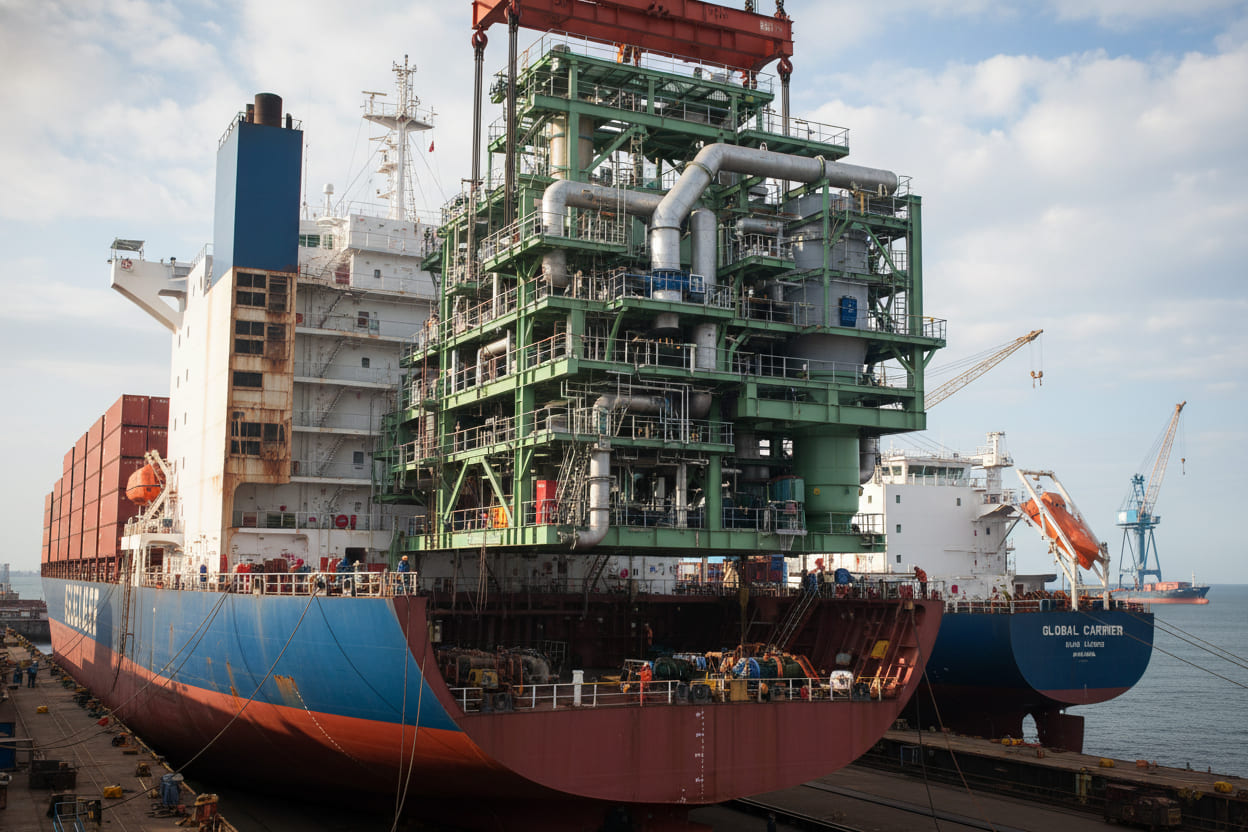
Case Study 2: Marine Vessel Exhaust Gas Cleaning
International Maritime Organization (IMO) 2020 regulations limiting marine fuel sulfur content to 0.5% presented compliance challenges for existing vessel fleets. A major container shipping operator evaluated scrubbing alternatives for 8,000 TEU vessels.
Solution Implemented:
- Open-loop seawater scrubbing systems with closed-loop operation in restricted waters
- Silicon carbide nozzle arrays resistant to saltwater corrosion
- Integrated washwater monitoring ensuring pH and turbidity compliance
Results Achieved:
- Continuous compliance with IMO Annex VI SO₂ limits
- Ability to continue burning lower-cost high-sulfur fuel oil (HSFO)
- Payback period of 18 months versus low-sulfur fuel alternative
Case Study 3: Refinery Fluid Catalytic Cracking Unit
A Gulf Coast refinery required SO₂ emission reductions from their fluid catalytic cracking (FCC) unit regenerator. Concentrations peaked at 1,200 ppmv during catalyst regeneration cycles, exceeding permitted levels by 40%.
Solution Implemented:
- Semi-dry spray dryer absorber with lime injection
- Fabric filter for particulate and reacted sorbent capture
- Automated reagent feed control responding to SO₂ concentration variations
Results Achieved:
- SO₂ emissions consistently below 50 ppmv (96% reduction)
- Minimal wastewater generation addressing site water balance constraints
- Integration with existing particulate control infrastructure reducing capital costs
Cross-Industry Performance Insights
Analysis across these diverse applications reveals common success factors for FGD implementation:
- Thorough front-end characterization of gas stream variability
- Conservative design margins accommodating operational upsets
- Material selection accounting for halide corrosion mechanisms
- Operator training emphasizing preventive maintenance disciplines
6. Frequently Asked Questions
What is the typical cost range for installing flue gas desulfurization equipment?
Capital costs for FGD systems vary substantially based on unit size, technology selection, and site-specific factors. Wet limestone systems typically range $120–$180 per kW of generating capacity, meaning a 500 MW coal unit might invest $60–90 million. Smaller installations or dry sorbent injection alternatives may achieve lower capital requirements of $20–50 per kW, though with reduced removal capabilities. Operating costs including reagent, power, and maintenance generally fall between $200–$500 per ton of SO₂ removed.
How does flue gas desulfurization differ from denitrification technology?
While FGD targets sulfur dioxide removal, denitrification addresses nitrogen oxides (NOₓ). The technologies differ fundamentally in their chemical approaches. FGD relies on absorption and acid-base neutralization, whereas denitrification typically employs selective catalytic reduction (SCR) or selective non-catalytic reduction (SNCR) using ammonia or urea to chemically reduce NOₓ to molecular nitrogen and water. Many facilities implement both technologies in series, with SCR/SNCR upstream controlling NOₓ and FGD downstream capturing SO₂. For comprehensive emission control solutions, facilities should evaluate integrated Desulfurization And Denitrification system designs.
Can existing FGD systems be upgraded for enhanced performance?
Yes, multiple upgrade pathways exist for aging FGD installations seeking improved efficiency or expanded capacity. Common modifications include:
- Adding spray levels or improving nozzle specifications for enhanced gas-liquid contact
- Installing forced oxidation systems converting waste sulfite to marketable gypsum
- Upgrading reagent preparation systems for finer particle size and faster reaction kinetics
- Implementing advanced process controls optimizing pH and stoichiometry in real-time
Data indicates that well-designed upgrades can improve removal efficiency by 2–5 percentage points while reducing reagent consumption 5–15%.
What materials offer optimal corrosion resistance in FGD environments?
FGD systems present aggressive corrosion conditions combining acidic chlorides, abrasive slurries, and elevated temperatures. Material selection critically impacts service life:
- 316L Stainless Steel: Standard for absorber vessels and piping; adequate for moderate chloride environments
- Alloy C-276: Premium nickel alloy for high-chloride applications or severe corrosion zones
- Rubber Linings: Cost-effective protection for carbon steel vessels in mild-to-moderate service
- Fiber-Reinforced Plastics (FRP): Excellent chemical resistance for ductwork and auxiliary piping
- Silicon Carbide: Superior for high-wear nozzle and slurry pump applications
How do FGD systems impact overall plant efficiency and water balance?
Wet FGD systems impose parasitic loads reducing net plant output by 1–3%. Primary energy consumers include slurry recirculation pumps (typically the largest load), flue gas fan overcoming additional pressure drop, and reagent preparation equipment. Water consumption varies dramatically by technology—wet systems requiring substantial makeup (0.5–2.0 m³/MWh), while dry systems consume negligible water. Facilities in water-constrained regions increasingly evaluate water treatment and zero-liquid discharge configurations, though these add capital and operating complexity.
7. Conclusion and Next Steps
Flue gas desulfurization stands as a mature, proven technology essential for industrial SO₂ emission control. Analysis of global installations demonstrates that well-engineered FGD systems consistently achieve 95%+ removal efficiencies while maintaining availability rates exceeding 98%. As regulatory frameworks continue tightening worldwide—from China's Ultra-Low Emission standards to the EU's evolving IED requirements—FGD technology will remain central to compliance strategies across power generation, refining, and manufacturing sectors.
The economic case for FGD implementation has strengthened considerably as reagent costs stabilize and byproduct markets develop. Facilities that previously deferred investment now face accelerating compliance deadlines and escalating penalty structures. Early movers benefit from equipment availability, construction scheduling flexibility, and avoided non-compliance exposure.
"The question for facility operators is no longer whether to install FGD capacity, but how to optimize system design for lowest life-cycle cost and maximum operational reliability." — Power Engineering International
For organizations evaluating flue gas desulfurization projects, three immediate actions can accelerate progress:
- Conduct Gap Analysis: Compare current emissions against applicable regulatory limits to quantify reduction requirements and establish project drivers
- Screen Technology Alternatives: Evaluate wet, dry, and emerging FGD approaches against site-specific constraints including footprint, water availability, and byproduct disposition
- Engage Experienced Partners: Select engineering firms and equipment suppliers with demonstrated FGD expertise in your specific industry and fuel type
The transition to cleaner industrial operations demands decisive action. With proper planning, technology selection, and execution, flue gas desulfurization delivers both environmental compliance and long-term operational value.