


Industrial Spray Nozzle Selection Guide: Types, Materials, and Applications for Cleaning, Cooling, and Coating
How to choose between internal mix and external mix, calculate cooling rate requirements, and avoid steam blanketing in alloy steel quenching
Target audience: Heat treatment engineers, metallurgists, process engineers, and production managers working with 4140, 4340, D2, 5160, 316L, and other special alloy steels.
Quick Selection Guide (30‑Second Read)
| Your primary requirement | Recommended nozzle type | Key specification to verify |
|---|---|---|
| Minimum droplet size (10‑30 µm) | Internal mix | Air pressure ≥60 psi, clean water (<5 µm filtration) |
| Harsh water / recirculated coolant | External mix | Orifice size ≥0.080″, air consumption 8‑15 SCFM |
| Fastest cooling rate (>40°C/s) | Internal mix, high pressure | Air 80‑95 psi, water 2‑5 GPM, ratio 15‑20:1 |
| Lowest compressed air cost | External mix with air‑saving design | 8‑12 SCFM @ 60 psi per nozzle |
| Preventing steam blanketing on hot steel (>800°C) | Internal mix or high‑velocity external | Droplet velocity >100 ft/s |
| Multi‑stage cooling profiles | Internal mix with adjustable air/water | Turndown ratio ≥20:1 |
Unsure? Jump to the Decision Matrix or Critical Parameters.
Table of Contents
- Air Atomizing Nozzles for Steel Heat Treatment: Overview
- Decision Matrix: Which Air Atomizing Nozzle Is Right for You
- Internal Mix vs External Mix: Detailed Trade‑offs
- Critical Selection Parameters for Alloy Steel Cooling
- 4.1 Droplet Size and Steam Blanket Penetration
- 4.2 Cooling Rate Control for Microstructure Management
- 4.3 Air Consumption and Operating Cost Calculation
- Selection Workflow: 6 Steps to Specify Your Nozzle
- Common Selection Mistakes (and How to Avoid Them)
- Maintenance and Lifecycle Cost Comparison
- When Air Atomizing Spray Is NOT the Right Choice
- Frequently Asked Questions
- Specification Checklist and Next Steps
1. Air Atomizing Nozzles for Steel Heat Treatment: Overview
 Air atomizing (two‑fluid) nozzles use compressed air to shear liquid water into micron‑sized droplets, then accelerate them toward the hot steel surface. Compared to hydraulic (pressure‑only) nozzles, they offer three decisive advantages for special alloy steel cooling:
-
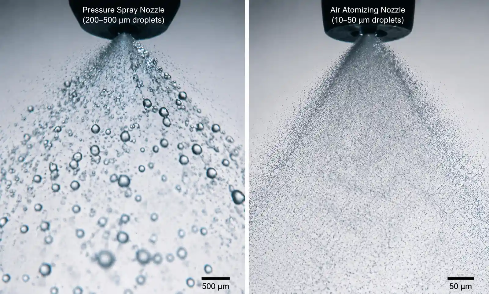
Penetration of the steam blanket – At steel temperatures above the Leidenfrost point (≈800°C for water), a continuous vapor layer forms. Larger droplets from pressure nozzles bounce off this layer; fine, high‑velocity atomized droplets punch through, maintaining liquid‑to‑metal contact.
-
Controllable cooling intensity – By independently varying air pressure (affects droplet size and velocity) and water flow rate, you can achieve cooling rates from 5°C/s to over 50°C/s – essential for phase transformation control (martensite, bainite, pearlite suppression).
-
Uniform surface cooling – The fine, widely distributed spray eliminates flooding and run‑off, reducing temperature variation across the part from >±15°C (pressure nozzles) to <±5°C.
This guide helps you select the correct air atomizing nozzle type, size, and operating parameters for your specific alloy steel grade, part geometry, and production environment.
2. Decision Matrix: Which Air Atomizing Nozzle Is Right for You
Use this matrix to narrow options based on your process conditions:
| Application scenario | Recommended type | Air pressure (psi) | Water flow (GPM per nozzle) | Expected cooling rate (°C/s) |
|---|---|---|---|---|
| D2 / A2 tool steel dies (precision quench, clean water) | Internal mix | 55‑65 | 1.5‑2.5 | 12‑18 |
| 4140 / 4340 shafts (25‑50 mm diameter) | Internal mix | 70‑85 | 2.0‑3.5 | 25‑35 |
| 5160 spring steel (three‑stage cooling) | Internal mix (programmable) | 40‑85 (variable) | 1.0‑2.5 (variable) | 5‑40 (staged) |
| 316L stainless plate (solution treatment >1000°C) | Internal mix (high velocity) | 85‑95 | 3.0‑5.0 | 50‑70 |
| Continuous casting secondary cooling (recirculated, scale‑bearing water) | External mix | 50‑70 | 4.0‑8.0 | 15‑30 |
| Forge cooling / scale‑heavy environment | External mix with large orifice | 40‑60 | 5.0‑10.0 | 8‑20 |
| Low air capacity plant (<200 SCFM total) | External mix (air‑efficient) | 50‑60 | 2.0‑4.0 | 10‑20 |
Example: You are heat treating 4140 shafts, 40 mm diameter, using filtered city water. Target cooling rate 30°C/s through 800‑500°C. → Internal mix, 75 psi air, 2.5 GPM water per nozzle, nozzle spacing 150‑200 mm.
3. Internal Mix vs External Mix: Detailed Trade‑offs
This is the single most important specification decision.
| Parameter | Internal Mix | External Mix |
|---|---|---|
| Mixing point | Air + water combined inside nozzle body | Separate until exit orifice |
| Droplet size range | 10‑30 µm (very fine) | 30‑80 µm (fine) |
| Droplet velocity | 100‑150 ft/s | 50‑100 ft/s |
| Minimum stable flow | Very low (excellent turndown) | Requires >30% of max flow |
| Clogging sensitivity | High – small internal passages | Low – larger orifices (≥0.080″) |
| Water quality required | <5 µm filtration, <50 ppm suspended solids | <50 µm filtration, can handle some scale |
| Typical air consumption (at 60‑80 psi) | 15‑25 SCFM per nozzle | 8‑15 SCFM per nozzle |
| Typical water flow | 0.5‑5.0 GPM | 2.0‑10.0 GPM |
| Spray pattern stability | Excellent down to 10% turndown | Degrades below 30% turndown |
| Best application | Precision quench, clean water, multi‑stage cooling | Harsh water, continuous casting, high flow rates |
| Relative cost per nozzle | $80‑200 | $45‑120 |
Selection rule of thumb:
- Clean water (filtered to ≤5 µm) and you need tight microstructure control → Internal mix
- Recirculated water, scale present, or you want lower air operating cost → External mix
Real‑world example: A continuous casting line using recirculated water with 100‑200 ppm suspended solids tried internal mix nozzles. Clogging occurred every 2‑3 weeks. Switching to external mix (0.080″ orifices) extended maintenance intervals to 6 months. Droplet size increased from 20 µm to 45 µm – still effective for secondary cooling, and air consumption dropped 40%.
4. Critical Selection Parameters for Alloy Steel Cooling
4.1 Droplet Size and Steam Blanket Penetration
At steel temperatures above 800°C, water instantly forms a stable vapor film (Leidenfrost effect). Droplets must have sufficient momentum (mass × velocity) to penetrate this film.
| Droplet size | Velocity (air‑assisted) | Momentum | Steam blanket penetration | Cooling efficiency |
|---|---|---|---|---|
| 200‑500 µm (pressure nozzle) | 10‑20 ft/s | Low | Poor – bounces off | Low |
| 50‑100 µm (external mix) | 50‑80 ft/s | Medium | Adequate for most | Medium‑high |
| 10‑30 µm (internal mix, high pressure) | 100‑150 ft/s | High | Excellent | Highest |
How to specify for high‑temperature quenching (850‑1050°C):
- Choose internal mix with air pressure ≥70 psi → droplet size ≤30 µm, velocity >100 ft/s
- For external mix (when water quality forces it), specify highest available air pressure (70‑90 psi) and use small air cap orifice to maximize velocity
Verification method: During commissioning, use a thermal camera to observe steam layer thickness. If visible vapor layer exceeds 2‑3 mm, increase air pressure or switch to finer atomization.
4.2 Cooling Rate Control for Microstructure Management
Different alloy steels require specific cooling rates through critical transformation ranges:
| Steel grade | Critical range (°C) | Desired cooling rate (°C/s) | Target microstructure | Recommended nozzle setup |
|---|---|---|---|---|
| 4140 / 4340 | 800‑500 | 25‑35 | Martensite (avoid pearlite) | Internal mix, 70‑80 psi, 2.0‑3.0 GPM |
| D2 (high carbon, high Cr) | 850‑550 | 12‑18 | Fine martensite + carbides | Internal mix, 55‑65 psi, 1.5‑2.5 GPM |
| 5160 spring steel | 800‑650: fast 650‑400: moderate 400‑200: slow |
30‑40 15‑20 5‑10 |
Fine pearlite → martensite → stress relief | Programmable air/water (three‑stage) |
| 316L austenitic | 1050‑700 | 50‑70 | Prevent carbide precipitation | Internal mix, 85‑95 psi, 3‑5 GPM |
| H13 hot work tool | 1000‑600 | 20‑30 | Uniform martensite | Internal mix, 65‑75 psi, 2.0‑2.5 GPM |
Three‑stage cooling example for 5160 spring steel (actual production data):
| Stage | Temperature range | Cooling rate target | Air pressure (psi) | Water flow (GPM) | Air/water ratio | Purpose |
|---|---|---|---|---|---|---|
| 1 | 870°C → 650°C | 40°C/s | 85 | 2.5 | 15:1 | Suppress ferrite formation |
| 2 | 650°C → 400°C | 15°C/s | 60 | 1.8 | 10:1 | Controlled martensite formation |
| 3 | 400°C → 200°C | 5°C/s | 40 | 1.0 | 8:1 | Minimize distortion and residual stress |
Result: 45% reduction in spring warpage compared to single‑rate pressure spray.
Selection parameter to verify: Turndown ratio (maximum controllable flow / minimum controllable flow). Internal mix nozzles achieve 20:1 or better; external mix typically 3:1‑5:1. For multi‑stage cooling, specify internal mix.
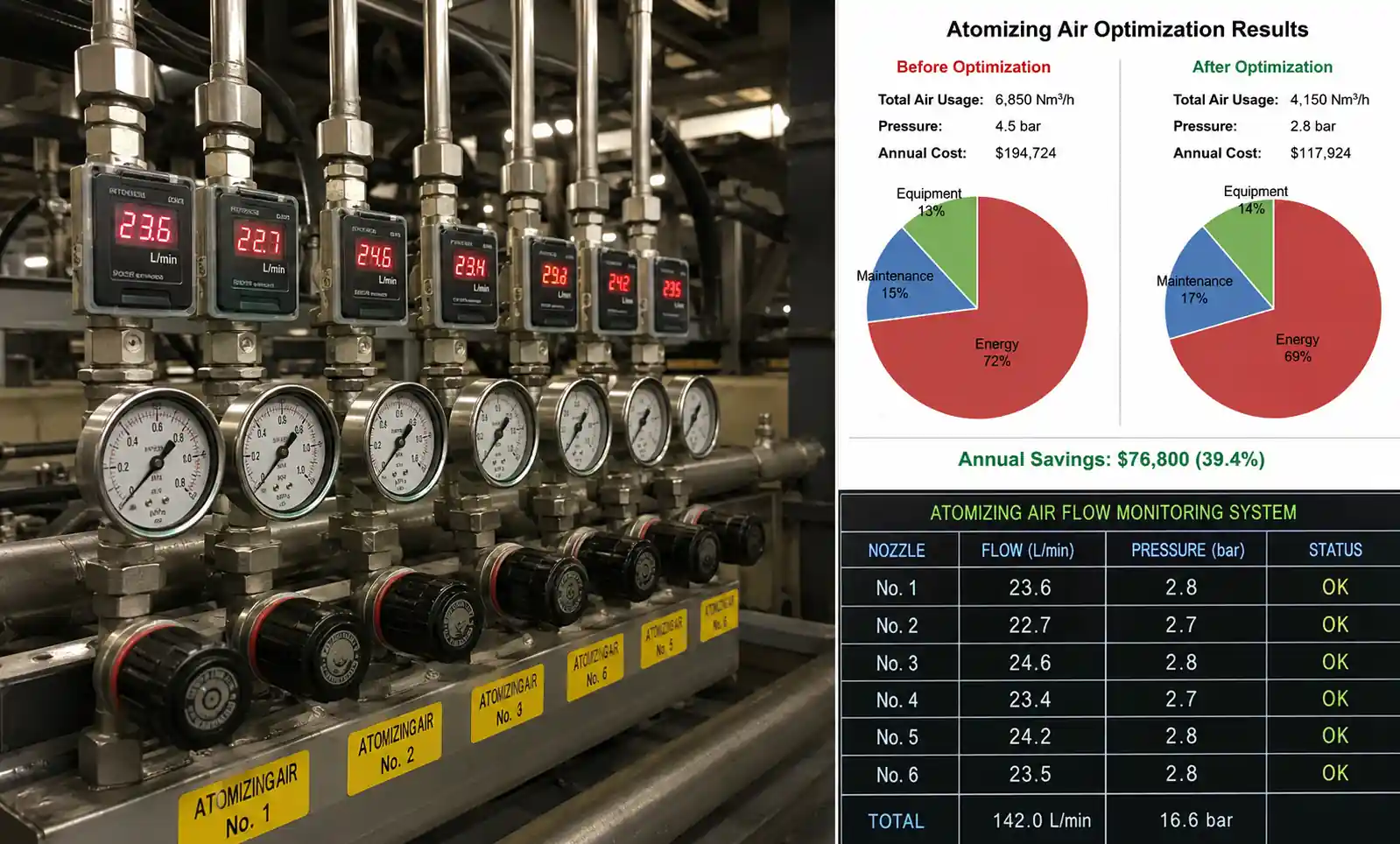
4.3 Air Consumption and Operating Cost Calculation
Compressed air is the largest operating expense for air atomizing systems. Calculate before selecting.
Formula:
Monthly air cost = (# nozzles) × (SCFM per nozzle) × (operating hours/day) × (days/month) × (air cost per 1000 SCF) Typical industrial air cost: $0.25‑0.40 per 1000 SCF (including compressor, dryer, maintenance).
Example comparison for a 40‑nozzle line, 16 hours/day, 22 days/month:
| Nozzle type | SCFM per nozzle | Total SCFM | Monthly air cost (@$0.30/MCF) |
|---|---|---|---|
| Standard internal mix (continuous) | 18 | 720 | $3,110 |
| Internal mix with demand control (9 hours avg) | 18 | 360 | $1,555 |
| External mix (continuous, 12 SCFM) | 12 | 480 | $2,075 |
| External mix with demand control | 12 | 240 | $1,037 |
| High‑efficiency internal mix (8 SCFM) | 8 | 320 | $830 |
How to minimize air cost without compromising cooling:
- Install part‑presence sensors – Only spray when steel is in the cooling zone (typical 40‑60% runtime reduction)
- Reduce air pressure in non‑critical zones – Thicker sections or less demanding metallurgy may tolerate lower pressure (and higher droplet size)
- Select air‑efficient nozzle designs – Newer multi‑stage atomizers produce similar droplet size at 30‑50% less air consumption
Payback example: Upgrading from standard internal mix (18 SCFM) to high‑efficiency internal mix (8 SCFM) on 40 nozzles. Extra cost: $4,200. Annual air savings: (10 SCFM reduction × 40 nozzles × 9 hr/day × 22 days × 12 months × $0.30/MCF) = $8,550. Payback: 5.9 months.
5. Selection Workflow: 6 Steps to Specify Your Nozzle
Use this checklist to document your requirements:
Step 1: Characterize your steel and process
- [ ] Steel grade(s): ____________
- [ ] Maximum section thickness: ____________ mm
- [ ] Austenitizing temperature: ____________ °C
- [ ] Target cooling rate through critical range: ____________ °C/s
- [ ] Desired microstructure: ____________ (martensite / bainite / fine pearlite)
Step 2: Define water quality and supply
- [ ] Water source: □ City / filtered □ Recirculated □ Well water
- [ ] Suspended solids concentration: ____________ ppm
- [ ] Particle size distribution: ____________ µm (90th percentile)
- [ ] Water temperature range: ____________ °C
- [ ] Available water pressure at nozzle inlet: ____________ psi
Step 3: Determine compressed air availability
- [ ] Plant air pressure (steady state): ____________ psi
- [ ] Available flow capacity for cooling zone: ____________ SCFM
- [ ] Air quality: □ Filtered □ Unfiltered □ Contains oil/moisture
Step 4: Select nozzle type (internal vs external mix)
- [ ] Water clean (<5 µm) AND need fine atomization → Internal mix
- [ ] Water has suspended solids OR want lower air consumption → External mix
Step 5: Size the nozzle
- [ ] Required water flow per nozzle: ____________ GPM (based on cooling rate and coverage area)
- [ ] Required air pressure to achieve target droplet size/velocity: ____________ psi
- [ ] Spray angle: □ 45° □ 60° □ 80° □ Other ___
- [ ] Nozzle spacing: ____________ mm (typically 1.5‑2× spray width)
Step 6: Verify with manufacturer data
- [ ] Request performance curve (droplet size vs air pressure for your water flow)
- [ ] Request material compatibility (303/316 stainless for most steels; Hastelloy for corrosive quenchants)
- [ ] Request sample nozzles for production trial
6. Common Selection Mistakes (and How to Avoid Them)
❌ Mistake #1: Choosing internal mix when water contains scale
Symptom: Nozzles clog weekly; spray pattern degrades; cooling non‑uniform.
Root cause: Internal passages (0.040‑0.060″) trap particles >50 µm.
Solution: Switch to external mix with 0.080″ or larger orifices. Or install 5 µm filtration upstream – but that may be cost‑prohibitive for high flow rates.
❌ Mistake #2: Under‑sizing air compressor capacity
Symptom: Air pressure drops during simultaneous nozzle operation; droplet size increases; cooling rate falls below target.
Root cause: Specified nozzle air consumption at 80 psi, but compressor cannot deliver peak flow.
Solution: Calculate total SCFM at maximum duty (all nozzles open simultaneously). Add 20% safety margin. Verify compressor FAD (free air delivery) at required pressure.
❌ Mistake #3: Ignoring steam blanket penetration for >800°C steel
Symptom: Surface temperature drops slowly; thermal imaging shows thick vapor layer; microstructure shows uneven transformation.
Root cause: Droplet velocity too low (<80 ft/s) for temperature above Leidenfrost point.
Solution: For steel >800°C, specify internal mix with air pressure ≥70 psi, or external mix with small air cap and pressure ≥80 psi. Request velocity data from manufacturer.
❌ Mistake #4: Using same nozzle for wide range of section thicknesses
Symptom: Thin sections crack; thick sections under‑cool (pearlite formation).
Root cause: Fixed cooling rate from single nozzle type/air pressure.
Solution: Use internal mix nozzles with wide turndown ratio (20:1). Install pressure regulators per zone. For mixed production, consider two independent cooling zones with different nozzle specifications.
❌ Mistake #5: Forgetting air line backflow prevention
Symptom: Water in air lines; check valves stuck; uneven spray.
Root cause: When nozzles cycle off, water can creep back into air manifold.
Solution: Specify air line purge valves that blow compressed air for 1‑2 seconds after each cooling cycle. Add check valves at each nozzle air inlet.
7. Maintenance and Lifecycle Cost Comparison
What wears out – and when
| Component | Typical life (clean water) | Typical life (harsh/recirculated water) | Replacement cost |
|---|---|---|---|
| Nozzle body (303/316 stainless) | >10,000 hours | >10,000 hours | $50‑150 (one‑time) |
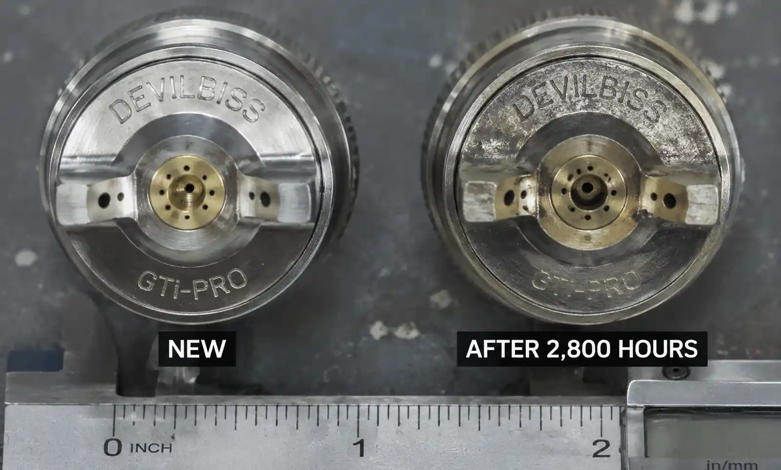
| Air cap (internal mix) | 6,000‑8,000 hours | 2,500‑3,500 hours | $18‑35 |
| Liquid cap / orifice (external mix) | 8,000‑10,000 hours | 3,000‑5,000 hours | $15‑25 |
| Check valves (air line) | 8,000‑10,000 hours | 4,000‑6,000 hours | $10‑20 |
| Filters (liquid side) | Replace per manufacturer | Replace 2‑3× more often | $5‑15 each |
Maintenance cost comparison: air atomizing vs hydraulic pressure nozzles
| Cost factor | Hydraulic pressure nozzles (old system) | Air atomizing (new system) |
|---|---|---|
| Nozzle replacement interval | 800‑1,200 hours (entire nozzle) | 6,000 hours (air caps only) |
| Annual replacement cost (40 nozzles) | $4,800‑$7,200 | $1,200‑$2,400 |
| Labor for maintenance | 8 hours/month | 3 hours/month |
| Compressed air cost | None | $1,000‑$2,500/month (dependent on control strategy) |
| Scrap reduction benefit | Baseline | 5‑10% reduction (offsets air cost) |
| Total annual operating cost (including scrap) | $15,000‑$20,000 | $12,000‑$18,000 (typically lower when scrap accounted) |
Recommended maintenance schedule for air atomizing nozzles:
- Weekly: Visual inspection of spray patterns (look for streaking or uneven coverage)
- Monthly: Remove and inspect 2‑4 critical‑zone nozzles; measure air cap orifice with pin gauge
- Quarterly: Clean all liquid filters; check air line drains; verify air pressure at each manifold
- Every 3,000 hours (harsh water): Replace air caps on all nozzles
- Every 6,000 hours (clean water): Replace air caps; rebuild check valves
8. When Air Atomizing Spray Is NOT the Right Choice
Despite their advantages, air atomizing nozzles are not universal. Do not specify them for:
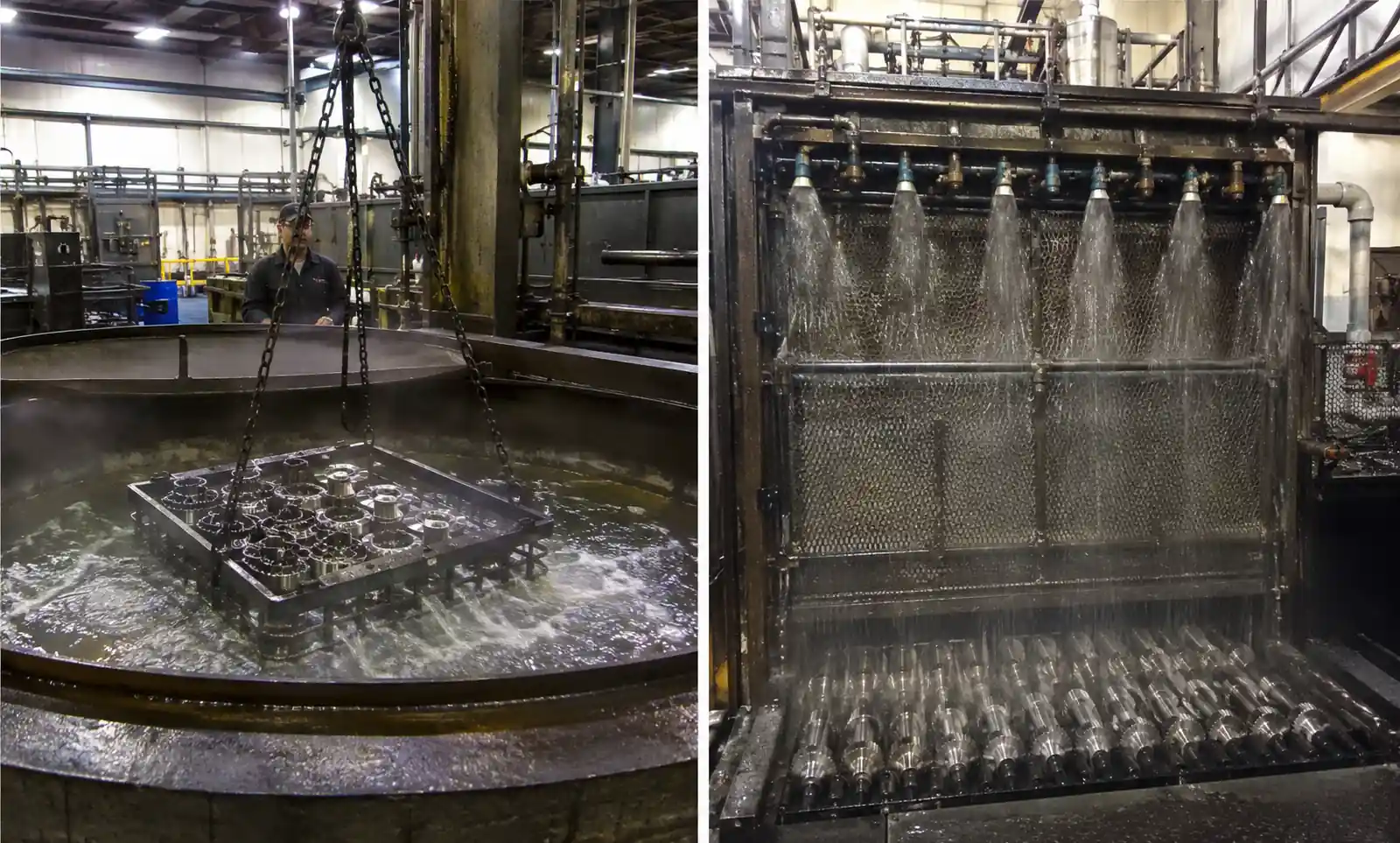
8.1 Large‑batch immersion quenching
If you are quenching 50+ parts simultaneously in a basket, immersion (oil, polymer, or water) is simpler, cheaper, and more consistent. Spray requires line‑of‑sight – parts shadow each other, creating uneven cooling.
Alternative: Submerged jet arrays or agitated immersion.
8.2 Very thin sections (<3 mm)
Ultra‑thin steel (sheet, foil, small stampings) cools so rapidly that even fine atomized spray can cause cracking due to thermal shock.
Alternative: Forced air cooling or mist cooling with larger droplets (≥100 µm).
8.3 Dirty water without filtration
If your cooling water contains >200 ppm suspended solids and you cannot install 5‑10 µm filtration, internal mix nozzles will clog constantly. External mix with 0.125″ orifices may work but droplet size will be coarse (>80 µm).
Alternative: Flood cooling with large‑orifice hydraulic nozzles.
8.4 Plants with severely limited compressed air
If your existing air system cannot provide the required SCFM and adding compressor capacity is not justified by scrap reduction, stick with hydraulic nozzles.
Rule of thumb: If total required air flow >500 SCFM and you have no existing large compressor, the capital cost ($50k‑$150k for new compressor + dryer) may exceed benefits.
8.5 Polymer quench applications
Some alloy steels require polymer quenchants (PAG solutions) to adjust cooling rate. Air atomizing nozzles are generally not compatible with viscous or non‑Newtonian fluids – internal passages clog, atomization quality degrades.
Alternative: Hydraulic nozzles with larger orifices designed for polymers.
9. Frequently Asked Questions
Q1: What droplet size is needed to penetrate the steam blanket on 900°C steel?
A: For steel above the Leidenfrost point (~800°C for water), droplet size should be ≤50 µm and velocity ≥80 ft/s. Internal mix nozzles at 70‑90 psi achieve 10‑30 µm and 100‑150 ft/s – ideal. External mix at 80‑90 psi gives 30‑50 µm and 70‑100 ft/s – adequate for most applications.
Q2: How do I calculate the number of nozzles needed for my cooling zone?
A: Determine required coverage area (length × width of steel passing through zone). Nozzle spacing typically equals 1.5‑2× the spray width at the target distance. For example, a nozzle with 80° spray angle placed 200 mm from the surface covers ≈335 mm diameter. Spacing 250‑300 mm leaves some overlap. Use manufacturer’s coverage charts.
Q3: Can I use air atomizing nozzles with polymer quenchants?
A: Generally not recommended. Most polymer solutions (PAG, PVP) have higher viscosity and surface tension than water, leading to poor atomization and clogging of small internal passages. Some specialty external mix nozzles with large orifices (≥0.125″) can work but test thoroughly.
Q4: What is the typical turndown ratio for cooling rate control?
A: Internal mix nozzles can achieve 20:1 turndown (e.g., 0.25‑5.0 GPM water flow) by varying air pressure and water flow independently. External mix typically achieves 3:1‑5:1. For multi‑stage cooling profiles (e.g., spring steel), specify internal mix with separate air and water regulators per zone.
Q5: How do I prevent nozzle clogging when using recirculated water?
A: Three options in order of preference:
- Install automatic backflushing filters (50‑100 µm) on the water supply.
- Switch to external mix nozzles with 0.080‑0.125″ orifices – they tolerate larger particles.
- Add a side‑stream magnetic separator for ferrous scale.
Q6: What is the actual compressed air cost per nozzle per year?
A: Formula: SCFM × operating hours/year × $0.30/1000 SCF × 60 min/hr. Example: 15 SCFM nozzle, 4,000 operating hours/year → 15 × 4,000 × 60 × 0.30/1000 = $1,080 per nozzle per year. Reducing air consumption by 5 SCFM saves $360/year per nozzle.
Q7: How do I verify that my selected nozzle achieves the required cooling rate?
A: Best method – instrumented production trial:
- Embed thermocouples in a test coupon of the same steel grade and section thickness.
- Heat to austenitizing temperature.
- Cool with the candidate nozzle at specified air/water settings.
- Record temperature vs time curve. Calculate cooling rate in critical range.
- Compare with metallurgical requirement (e.g., >25°C/s for 4140 martensite).
Q8: What materials are available for nozzle construction?
A:
- 303/304 stainless steel – standard for clean water, most alloy steel applications.
- 316 stainless – for corrosive environments (chlorides, acidic quenchants).
- Hastelloy C‑276 – for severe corrosion or high‑temperature oxidizing conditions.
- Hardened tool steel – for abrasive service (external mix orifices only).
10. Specification Checklist and Next Steps
Final specification checklist for purchasing
Copy this into your RFQ:
AIR ATOMIZING NOZZLE SPECIFICATION – ALLOY STEEL HEAT TREATMENT
Required cooling performance:
- Steel grade(s): ____________________
- Austenitizing temperature: _________ °C
- Required cooling rate (critical range): _________ °C/s
- Target droplet size (max): _________ µm
- Steam blanket penetration required? □ Yes (T >800°C) □ No
Nozzle type: □ Internal mix □ External mix
Water supply:
- Flow rate per nozzle: _________ GPM
- Water quality: □ Clean (<5 µm) □ Harsh (suspended solids up to _______ ppm)
- Water temperature: _________ °C
Air supply:
- Inlet pressure available: _________ psi
- Maximum SCFM per nozzle: _________ (if known)
Spray geometry:
- Spray angle: _________ degrees
- Distance to target: _________ mm
- Coverage width required: _________ mm
Construction:
- Material: □ 303 SS □ 316 SS □ Hastelloy □ Other _________
- Connection size: _________ (e.g., 1/4″ NPT, 3/8″ BSPT)
Accessories required: □ Air cap replacement kit (quantity: ______) □ Liquid filters (micron rating: ______) □ Check valves (air line) □ Mounting brackets (description: ______)
Quantity: _________ nozzles Delivery required by: _________
Include with quotation: □ Performance curve (droplet size vs air pressure at specified water flow) □ Dimensional drawing □ Material certificate
Next steps after selection
-
Request samples – Test on your actual steel grade and production temperature. Do not rely solely on published curves.
-
Design the manifold – Air and water distribution lines must be sized for peak flow. Provide individual shut‑off valves and pressure regulators per zone.
-
Install filtration – For internal mix, install 5‑10 µm filters on water line. For external mix, 50‑100 µm is usually sufficient.
-
Commission with thermal validation – Use thermal imaging or embedded thermocouples to verify cooling uniformity and rate.
-
Train maintenance staff – Show them how to inspect, clean, and replace air caps. Keep spare air caps on hand.
-
Monitor and optimize – After 3 months, review scrap rates, cycle times, and compressed air consumption. Adjust air pressure downward in zones where possible.
Summary: One‑Page Selection Guide
| If you need... | Choose... | Key spec |
|---|---|---|
| Very fine droplets (10‑30 µm) for thin sections or high‑temperature quenching | Internal mix, 70‑90 psi | Droplet size curve |
| Low air consumption (<12 SCFM per nozzle) | External mix or high‑efficiency internal | SCFM rating at 60 psi |
| Multi‑stage cooling profile (e.g., spring steel) | Internal mix with separate air/water controls | Turndown ratio ≥20:1 |
| Tolerance to scale or recirculated water | External mix, 0.080″+ orifice | Orifice size |
| Lowest initial purchase cost | External mix (standard) | $45‑120 per nozzle |
| Lowest total operating cost (air + scrap reduction) | Internal mix with demand control and efficient air cap | Calculate payback |
Final recommendation for most alloy steel heat treatment (4140, 4340, D2, 5160):
Start with internal mix nozzles (60‑80 psi), 1.5‑3.0 GPM water per nozzle, spacing 150‑200 mm. Use filtered water (≤10 µm). Install part‑presence sensors to reduce air consumption. Verify cooling rate with thermocouple‑instrumented test coupons.