How to Prevent Nozzle Clogging in Cleaning Systems (2026)
If you manage parts washing systems, tank cleaning equipment, or CIP circuits, you already know: a clogged nozzle creates incomplete cleaning, contamination carryover, rejected batches, and unplanned downtime. Nozzle clogging accounts for roughly 40% of cleaning system downtime, yet most facilities treat it as unavoidable rather than an engineering problem with known solutions. This guide covers clog-resistant nozzle selection, correct filtration sizing, chemical compatibility, and predictive maintenance that catches partial blockages before they cause quality issues.
Table of Contents
- Root Causes of Nozzle Clogging
- Filtration: Your First Line of Defense
- Nozzle Selection Strategy for Clog Resistance
- Material Compatibility and Chemical Attack
- Maintenance Protocol That Actually Works
- System Design Decisions
- FAQ
- Conclusion
1. Root Causes of Nozzle Clogging
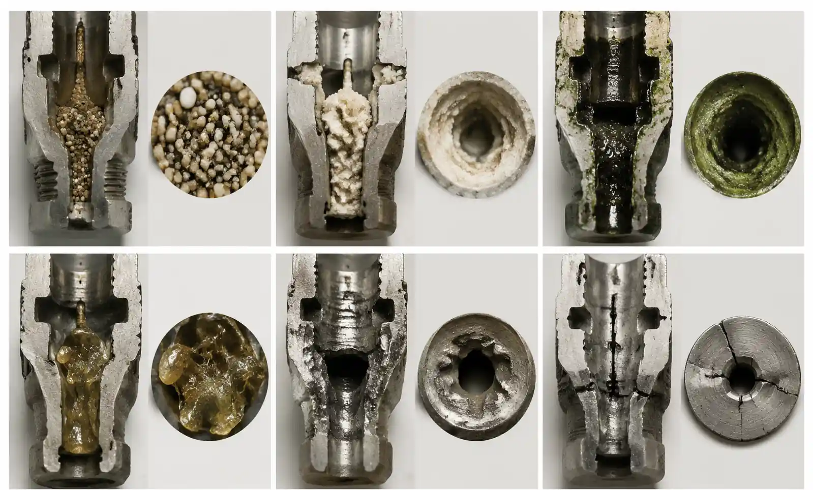
Clogging falls into six mechanisms, each requiring different countermeasures.
Particulate Blockage: Debris in the fluid stream lodges in the orifice or vanes—metal fines, abrasive media, rust scale, product solids, or mineral scale. Rule: The smallest internal passage should be at least 3-4× larger than the 95th percentile particle size. If you have 200-micron particles, you need nozzles with 600+ micron throats.
Chemical Precipitation and Scaling: Dissolved salts, surfactants, or multi-component chemistries precipitate inside the orifice—sodium carbonate crystallizing as caustic wash cools, or calcium sulfate precipitating when sulfuric acid reacts with hard water calcium.
Biological Growth and Biofilm: In water-based systems operating intermittently below 60°C, bacterial biofilms colonize nozzle internals—especially in parts washers idle over weekends.
Polymer and Resin Crosslinking: Residual chemistry in wash fluid crosslinks or polymerizes inside the nozzle, especially in low-flow dead zones.
Cavitation Erosion and Secondary Debris: In high-pressure systems (>1,000 PSI), cavitation erodes internal surfaces; eroded metal particles recirculate and lodge in downstream nozzles.
Freezing and Thermal Shock: Residual water freezes and expands, cracking internal vanes or distorting orifices.
Key takeaway: Effective clog prevention requires diagnosing the dominant mechanism. Particulate clogs need filtration upgrades; chemical precipitation needs fluid chemistry control; biofilm needs biocide or temperature increase.
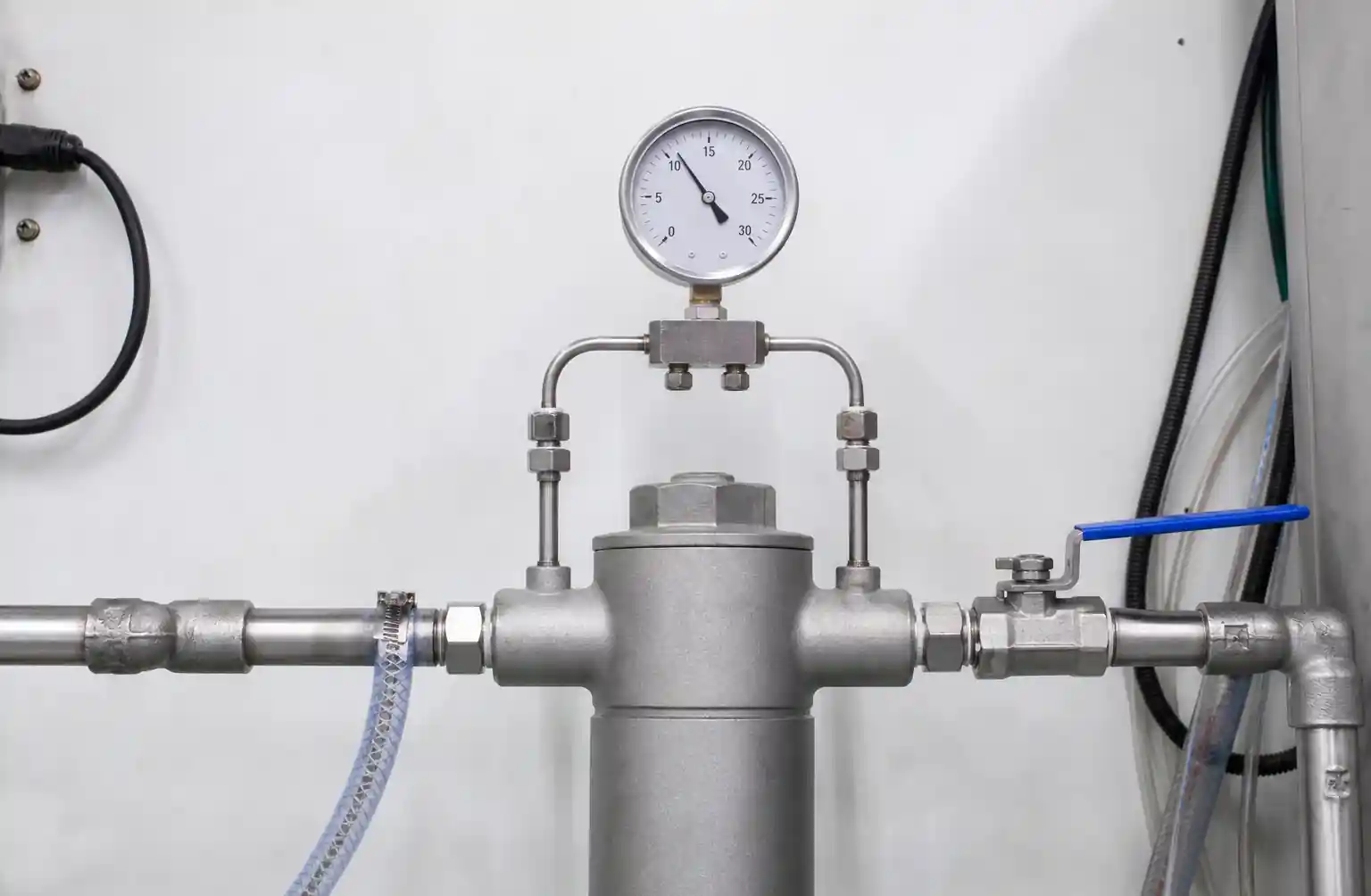
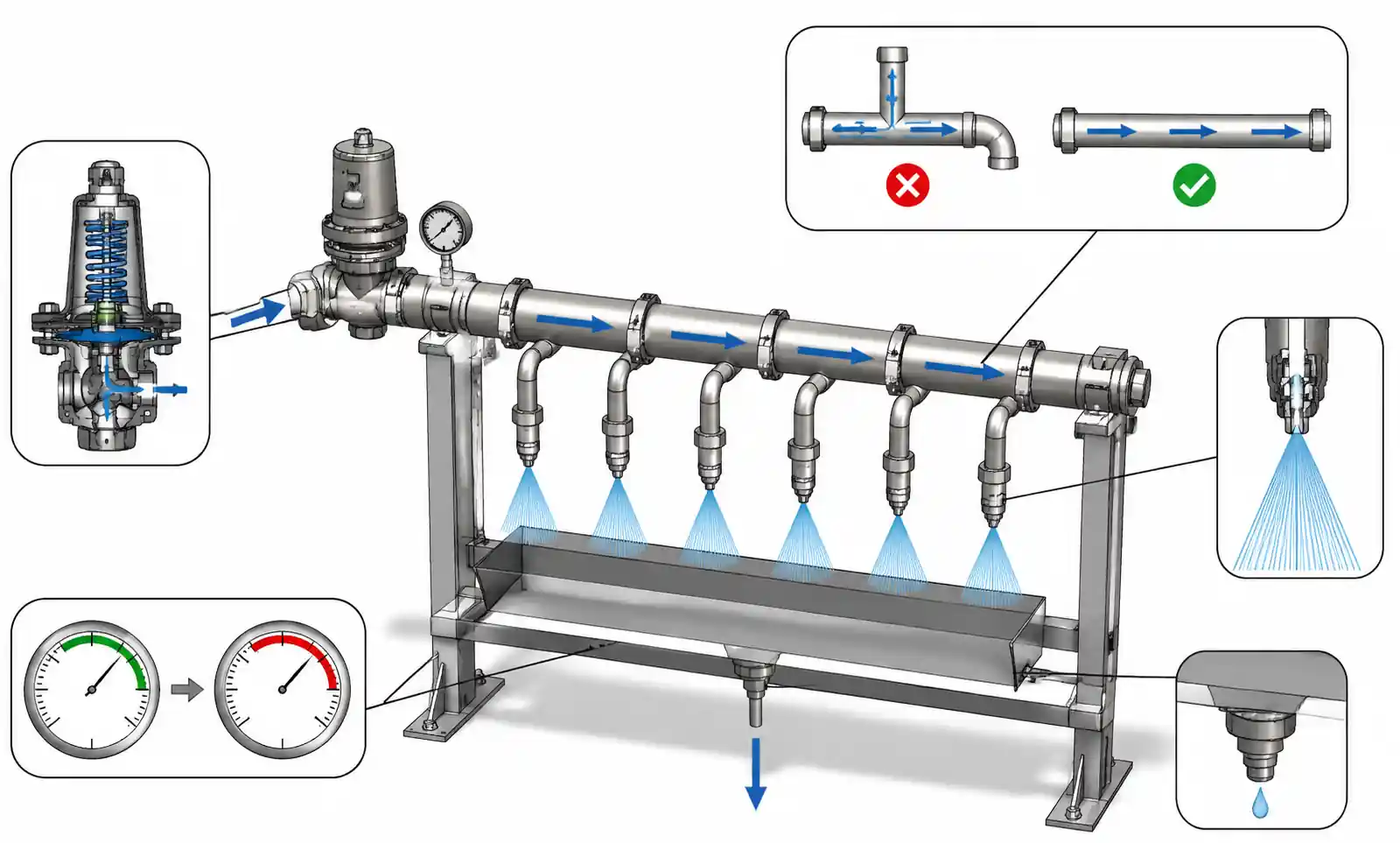
2. Filtration: Your First Line of Defense
Most clogging is preventable with correctly sized and maintained filtration. Filtration is often specified for pump protection rather than nozzle protection, leading to filters that are too coarse.
Filtration Micron Rating vs. Nozzle Orifice Size
Rule: Filtration cutoff = (smallest nozzle passage) / 3
For flat fan nozzles with 0.8 mm orifices: 250-micron filtration minimum. For full cone with 1.5 mm: 500-micron baseline. For air atomizing with 0.3 mm liquid passages: 100-micron or finer.
| Nozzle Type | Typical Orifice Size | Minimum Filtration | Preferred Filtration | Notes |
|---|---|---|---|---|
| Flat fan (standard) | 0.8–1.5 mm | 250–500 micron | 100–200 micron | Slot dimension is critical path |
| Full cone (hydraulic) | 1.2–2.5 mm | 400–800 micron | 200–400 micron | Vane spacing limits particle size |
| Hollow cone (spiral) | 1.0–2.0 mm | 300–600 micron | 150–300 micron | Spiral vanes trap elongated particles |
| Air atomizing (internal mix) | 0.3–0.6 mm | 100–200 micron | 50–100 micron | Both air and liquid passages must be protected |
| Tank cleaning rotary | 3.0–8.0 mm | 1,000–2,500 micron | 500–1,000 micron | Bearing clearances are tighter than orifices |
Filtration Efficiency: A "200-micron filter" might only capture 50% of 200-micron particles. Target Beta ratio β₂₀₀ ≥ 75 (captures 98.7% at 200 microns).
Filter Placement: Install the final filter within 3 meters of nozzles to minimize recontamination. Eliminate filter bypasses—unfiltered fluid during pressure spikes will clog nozzles immediately. Monitor differential pressure; replace when ΔP reaches 15 PSI.
3. Nozzle Selection Strategy for Clog Resistance
Not all nozzles clog equally. Some designs inherently tolerate more contamination.
Orifice Diameter: Bigger Is More Reliable. Moving from 1.0 mm to 1.5 mm orifice reduces clog frequency by ~60% in field data, even with identical filtration. If cleaning performance allows 20-30% higher flow, upsize nozzles.
| Nozzle Type | Clog Resistance | Smallest Passage | Common Clog Point | Best Application |
|---|---|---|---|---|
| Full cone (vane) | Low | Vane slots (60-70% of orifice) | Vane tips | Tank cleaning, gross washing |
| Flat fan (elliptical) | Medium | Orifice throat width | Orifice edges/corners | Surface cleaning, rinsing |
| Hollow cone (spiral) | Low | Spiral chamber clearance | Spiral vanes | Cooling, gas scrubbing |
| Straight stream | High | Single round orifice | Orifice entrance | High-pressure jetting |
| Air atomizing | Very Low | Liquid and air ports | Liquid port | Fine spray coating |
| Flood jet | Very High | Wide open orifice | Rarely clogs | Low-pressure flooding |
Self-cleaning designs with rounded internal passages, electropolished internals, removable cores, or tangential entry vanes show 30-50% improvement in time-to-clog but cost 2-3× more. Payback is favorable if downtime exceeds $500/hour or nozzle access requires scaffolding.
4. Material Compatibility and Chemical Attack
Chemical attack roughens internal surfaces, creating nucleation sites for deposits and particle traps.
| Cleaning Chemistry | pH Range | Temperature | Avoid | Acceptable | Preferred |
|---|---|---|---|---|---|
| Alkaline detergents (NaOH, carbonates) | 11–14 | 60–90°C | Aluminum, brass | Stainless 316 | Hastelloy, PEEK |
| Acidic cleaners (phosphoric, citric) | 2–4 | 20–60°C | Carbon steel, brass | Stainless 316 | Stainless 316L, PVDF |
| Chlorinated solvents | N/A | 20–40°C | Brass, aluminum | Stainless 316 | Hastelloy, PTFE |
| Aqueous with high chlorides | 6–8 | 40–70°C | Stainless 304 | Stainless 316L | Duplex, titanium |
| Organic solvents (IPA, acetone) | N/A | 20–50°C | EPDM seals | Stainless 304/316 | Stainless 316, PTFE |
| High-purity water (DI, RO) | 6–7 | 20–80°C | Carbon steel, brass | Stainless 316L EP | Stainless 316L EP, PFA |
Hardness-related clogs: When water with 200+ ppm hardness is heated above 60°C, calcium carbonate precipitates in the orifice. Countermeasures: water softening to <50 ppm, pH adjustment to 6.5-7.0, scale inhibitors (5-10 ppm polyphosphates), or keeping fluid below 55°C.
5. Maintenance Protocol That Actually Works
Predictive maintenance catches partial clogs before they affect cleaning quality.
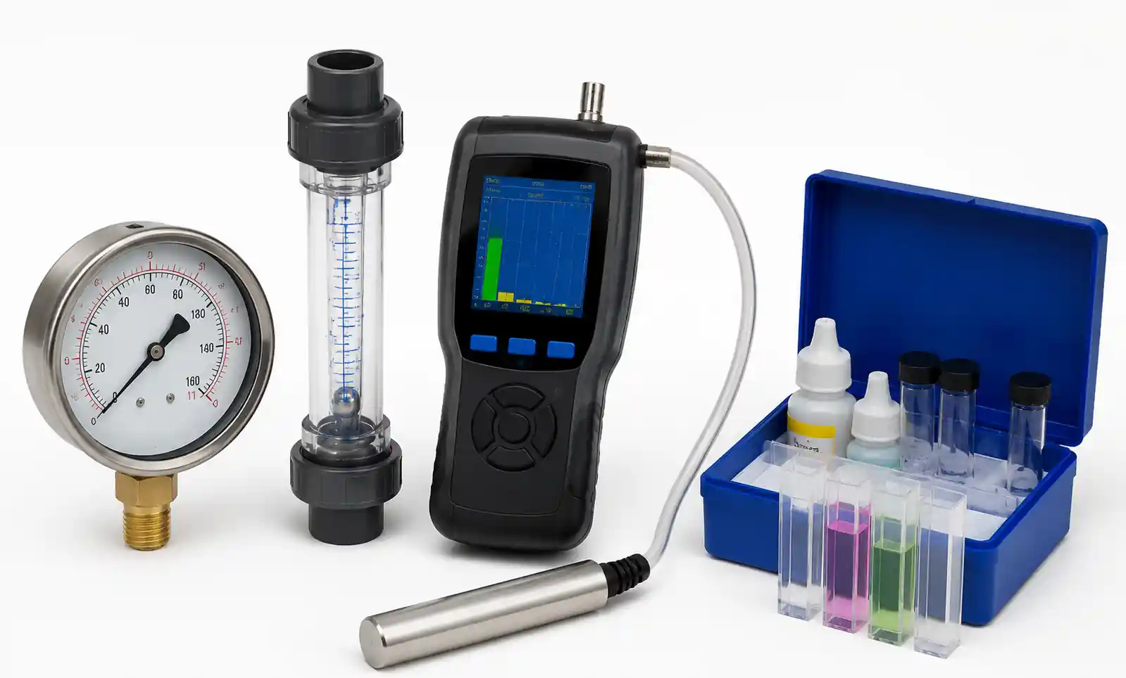
Flow Testing: Establish baseline flow for each nozzle/circuit when new, then measure quarterly. A 10% flow drop indicates partial clogging; 20% drop requires immediate replacement or cleaning. For rotary nozzles, measure rotation speed—15% speed reduction indicates imminent failure.
Cleaning Methods:
- Reverse flow purging: Apply line pressure (80-100 PSI) in reverse through the nozzle discharge—clears 60-70% of particulate clogs.
- Ultrasonic cleaning: Submerge in water/solvent at 40 kHz for 10-15 minutes—clears 80-90% of particulate and light scale.
- DO NOT use wire or drill bits to ream orifices—this damages edges and accelerates re-clogging.
- Chemical scale: Soak in 10% citric acid at 50°C for 2-4 hours (carbonate), or EDTA-based descaler (sulfate). Thoroughly rinse after.
Replacement Trigger: Replace when flow is >25% below baseline, spray angle has narrowed >10 degrees, visible corrosion or erosion exists, or nozzle has been cleaned >3 times.
6. System Design Decisions That Prevent Clogs
Velocity Maintenance: Maintain minimum 1.5 m/s (5 ft/s) velocity in distribution piping to keep particles suspended. Pipe diameter = √[(4 × Q) / (π × v)] where Q = flow in L/s, v = velocity in m/s.
Dead Leg Elimination: Any dead leg accumulates sediment that later flushes into nozzles. Use swept tees instead of straight tees. For bottom-mounted nozzles, bring supply pipe up from below.
Drain Points: Install drain valves at all low points. Before each production run, open drains for 15-30 seconds to purge settled particles.
Pressure Regulation: Install pressure regulators downstream of pumps to limit maximum pressure to 110% of design pressure. Use soft-start VFDs on pumps.
7. FAQ
How often should I replace nozzles even if not clogged?
In non-abrasive applications, stainless steel nozzles can last 5+ years. In abrasive or high-pressure applications, inspect annually and replace when flow increases >10% (indicates wear). Worn nozzles clog more easily.
Can I use magnetic filters?
Only for ferrous particles—captures 40-60% of contamination in machining parts washers. Still need cartridge filtration for non-magnetic particles.
Best way to clean nozzles in place?
Install a backflush manifold to reverse flow through nozzles using clean water at line pressure. Run for 30 seconds before each production cycle—prevents 70-80% of particulate clogs.
Strainers vs cartridge filters?
Strainers (mesh screens) suit coarse filtration (>500 micron). For most parts washing and CIP with orifices under 2 mm, use cartridge filters for finer cutoff and higher dirt capacity.
Why do nozzles clog more in winter?
(1) Cold makeup water increases viscosity, slowing particle settling. (2) Residual water freezes overnight, causing microcracking. Solutions: heat trace distribution piping, increase settling time, or purge nozzles with compressed air after each shift.
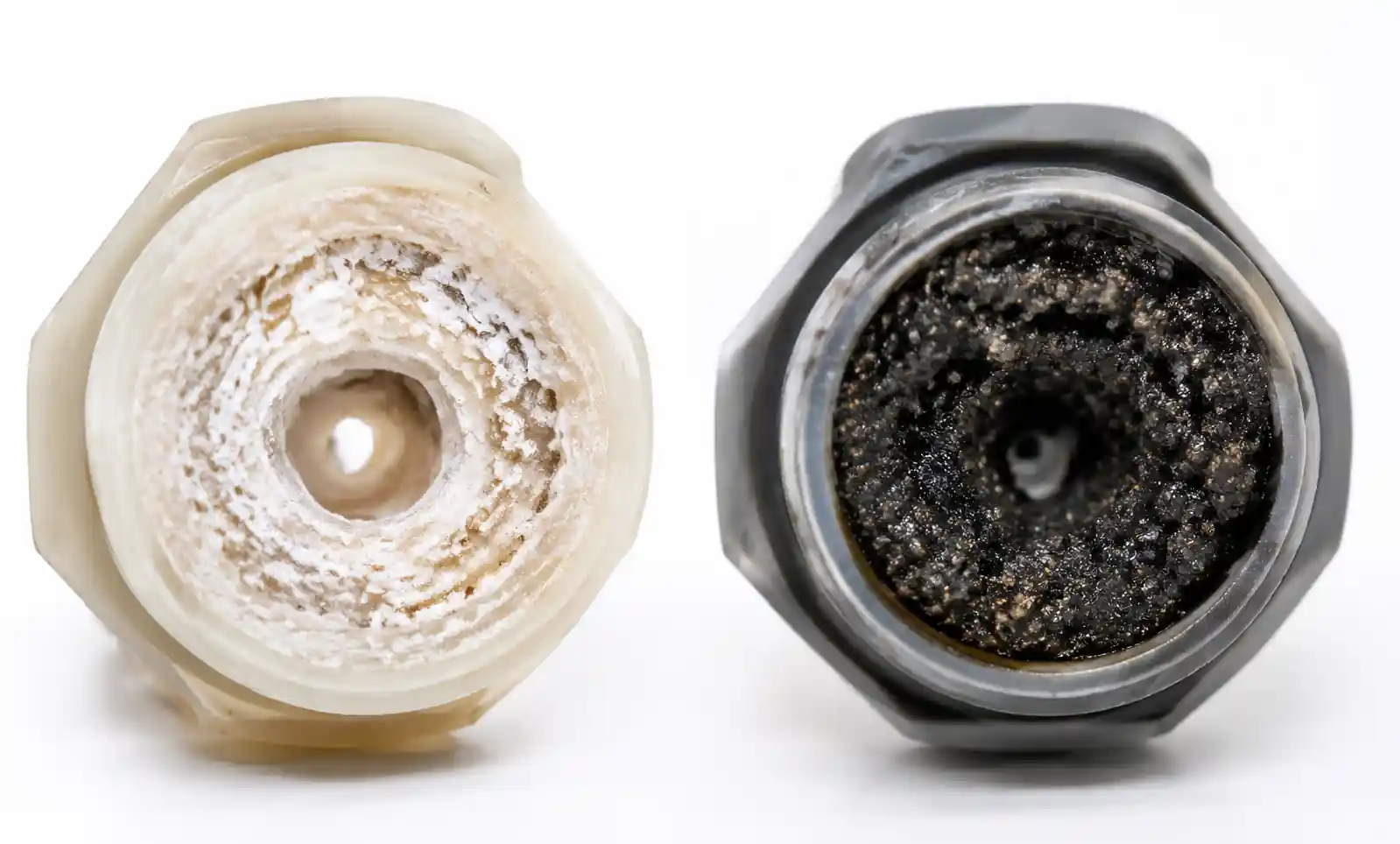
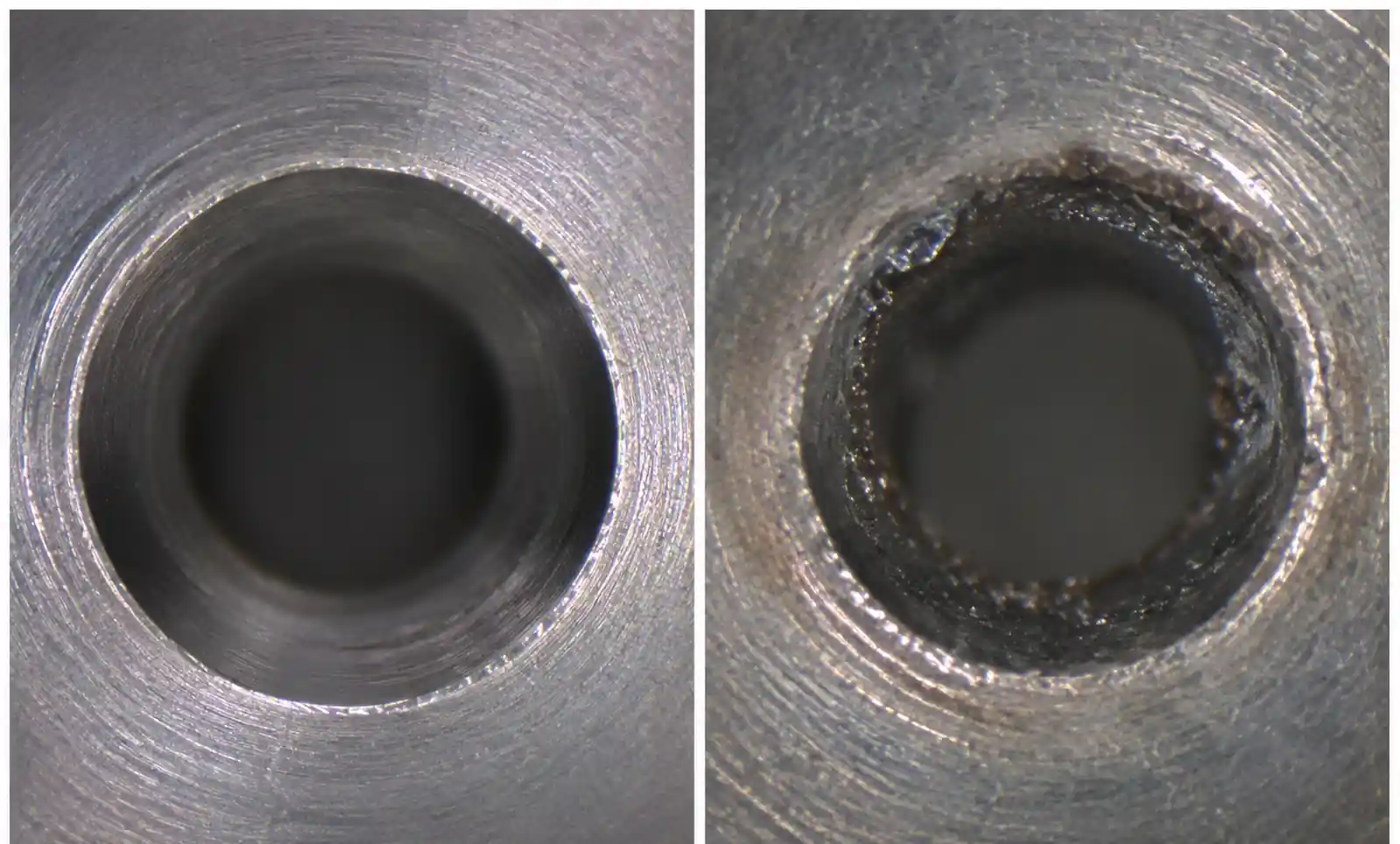
How to tell if clogging is from particles or chemical scale?
Remove and inspect. Particulate clogs are dark, granular, easy to dislodge. Chemical scale is white/colored, hard, crystalline, adhered. Carbonate scale fizzes with vinegar or citric acid.
8. Conclusion
Nozzle clogging is preventable. In nearly every case, clogs trace to undersized filtration, poor material selection, chemical incompatibility, or system design allowing particle settling. Targeted fixes—upgrading filtration micron ratings, selecting nozzles with larger orifices, treating water hardness, and implementing flow-based predictive maintenance—typically reduce clog frequency by 70-90% and pay back within 6-12 months.