


How to Choose Spray Nozzles for Shipbuilding Applications
Shipbuilding operations demand precision spraying across dozens of critical applications—from steel plate surface preparation and weld cooling to cargo tank cleaning and fire suppression systems. A poorly specified nozzle can lead to uneven coating coverage, extended drying times, premature wear in abrasive blasting, or failed IMO compliance in tank washing systems. This guide walks you through the engineering considerations, performance parameters, and material selection criteria that determine nozzle longevity and process reliability in marine fabrication and vessel outfitting.
Table of Contents
- Critical Spray Parameters for Marine Applications
- Nozzle Type Comparison for Shipbuilding Processes
- Material Selection and Corrosion Resistance
- Application-Specific Selection Guide
- Installation and Maintenance Considerations
- Total Cost of Ownership Analysis
- Frequently Asked Questions
- Conclusion and Next Steps
1. Critical Spray Parameters for Marine Applications
Selecting spray nozzles for shipbuilding requires balancing four primary parameters: flow rate, operating pressure, spray angle, and droplet size distribution. Each parameter directly impacts coating quality, cooling efficiency, or cleaning effectiveness.
Flow Rate and Coverage Area
Flow rate (typically measured in gallons per minute or liters per minute) determines how quickly you can cover a target surface. For steel plate pre-treatment wash-down before painting, we typically specify 0.5–2.0 GPM per nozzle at 40 PSI to achieve 80–120 square feet per minute coverage. Higher flow rates reduce cycle time but increase water consumption and disposal costs—critical in dry dock operations where wastewater treatment capacity is limited.
The relationship between pressure and flow follows the hydraulic equation Q = K × √P, where K is the nozzle flow coefficient. Doubling pressure only increases flow by approximately 1.41x, not 2x. Understanding this square-root relationship prevents over-sizing pumps and helps predict performance degradation as nozzles wear and orifices enlarge.
Operating Pressure and Impact Force
Pressure dictates both flow rate and spray impact force. For cargo tank cleaning in chemical tankers, IMO requirements typically mandate minimum impact forces of 7–12 N at the tank wall (measured at the farthest reach point) to dislodge cargo residues. This translates to operating pressures of 80–150 PSI for rotary tank cleaning machines, depending on nozzle design and tank geometry.
In contrast, post-weld cooling applications require gentle, uniform spray to avoid thermal shock cracking in thick steel sections. We recommend operating pressures below 30 PSI with full cone nozzles producing 200–400 micron droplets for controlled evaporative cooling without excessive runoff.
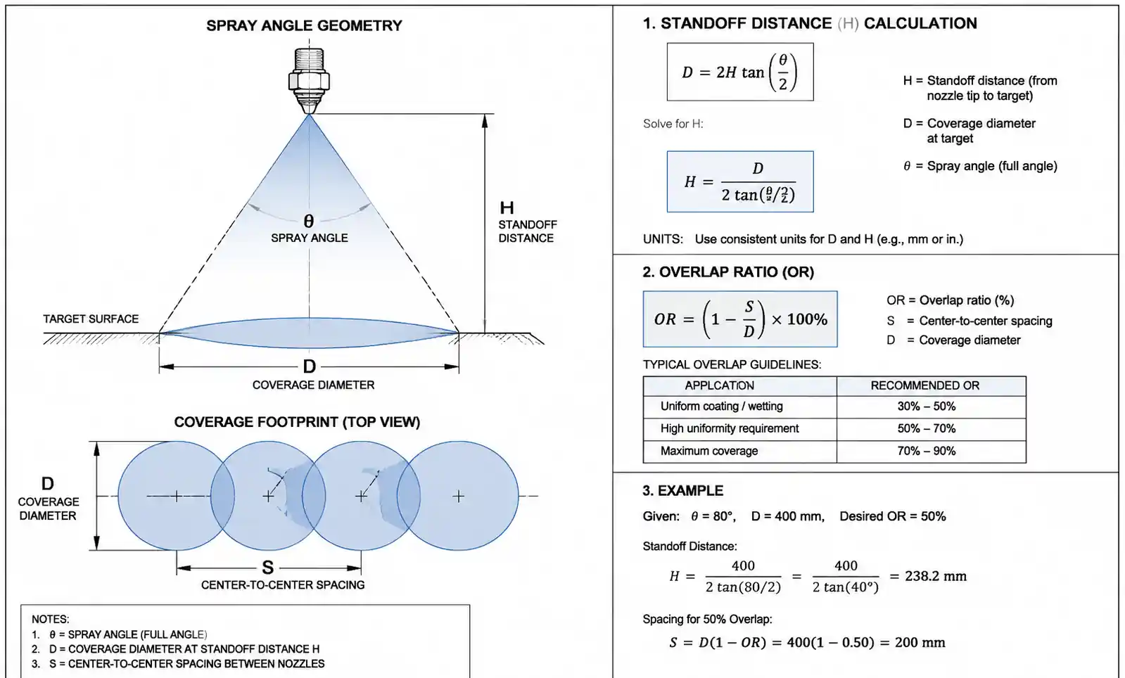
Spray Angle and Coverage Overlap
Spray angle (typically 15° to 120° for hydraulic nozzles) determines the footprint width at a given standoff distance. For automated coating booths in shipyards, we calculate overlap ratio using the formula:
Overlap (%) = [(S - H × tan(θ/2) × 2) / (H × tan(θ/2) × 2)] × 100
Where S = nozzle spacing, H = standoff height, θ = spray angle.
Most coating applications require 50–100% overlap to ensure uniform film thickness. Under-overlapping creates dry stripes; over-overlapping wastes material and extends flash-off time. For a 40° flat fan nozzle at 18-inch standoff, optimal spacing is 10–12 inches for 50% overlap.
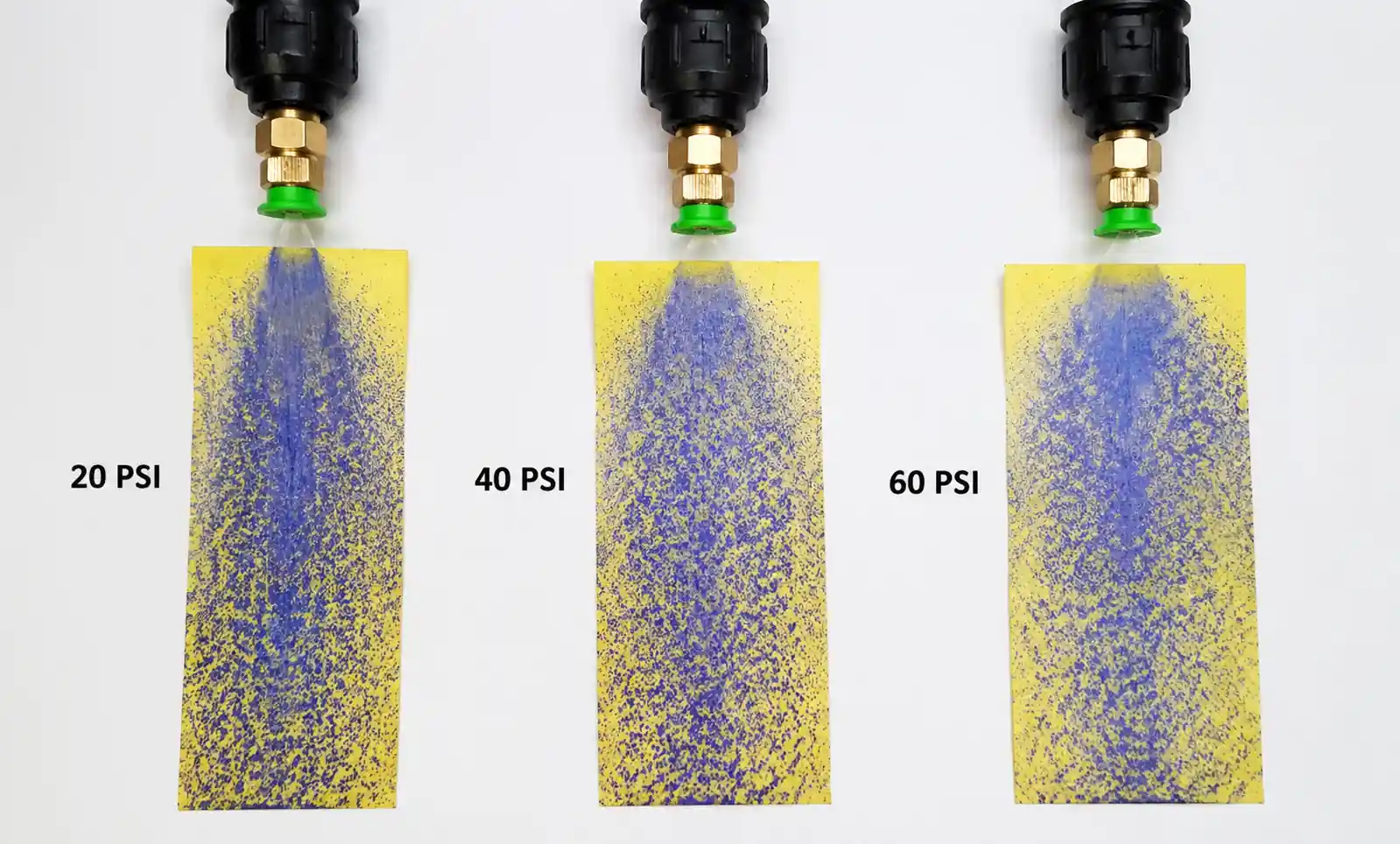
Droplet Size Distribution
Droplet size (characterized by Dv0.5 or Dv0.9 values from laser diffraction analysis) affects evaporation rate, surface wetting, and penetration into crevices. Fine atomization (50–150 microns) benefits fire suppression systems where rapid evaporative cooling is desired. Coarse spray (300–800 microns) works better for rinsing operations where you need droplet momentum to displace contaminants without creating aerosol mist that spreads particulates throughout the fabrication hall.
In our field testing of anti-corrosive primer application, nozzles producing 180–250 micron droplets at 35 PSI delivered optimal film build without excessive overspray or sagging on vertical bulkheads.
2. Nozzle Type Comparison for Shipbuilding Processes
Different spray patterns suit different shipbuilding tasks. Selecting the wrong pattern type is one of the most common specification errors we encounter during process audits.
| Nozzle Type | Spray Pattern | Typical Flow Range | Best Applications | Impact Force | Clogging Risk |
|---|---|---|---|---|---|
| Flat Fan | Elliptical, tapered edges | 0.05–5 GPM | Surface washing, coating (flat surfaces), rinsing conveyor-carried parts | Medium (concentrated at center) | Low (if filtered to 150 mesh) |
| Full Cone | Circular, uniform distribution | 0.1–50 GPM | Cooling (welded joints, heat-treated sections), quenching, fire suppression | Low to medium (distributed) | Medium |
| Hollow Cone | Ring-shaped, open center | 0.05–10 GPM | Tank washing (centrifugal force aids cleaning), evaporative cooling, gas scrubbing | High (at periphery) | Low |
| Solid Stream | Concentrated jet | 0.5–100 GPM | High-pressure descaling, cutting, hydro-blasting | Very high | Very low |
| Air Atomizing | Fine mist, controlled droplet size | 0.01–2 GPM | Precision coating (small parts), mold release, lubricant application | Very low | High (requires clean, dry air) |
Flat Fan Nozzles for Coating Lines
Flat fan nozzles produce an elliptical pattern with the highest flow density at the centerline, tapering toward the edges. This makes them ideal for automated coating systems where multiple nozzles are arranged in a manifold to cover wide panels. The tapered edge profile aids in achieving smooth overlap without creating thick buildup zones.
We specify even spray angle distribution flat fans (formerly called "even flat spray" in BETE nomenclature) for primer and topcoat application on pre-cut steel panels. Standard flat fans with their natural taper work well for rinsing where some variation is acceptable.
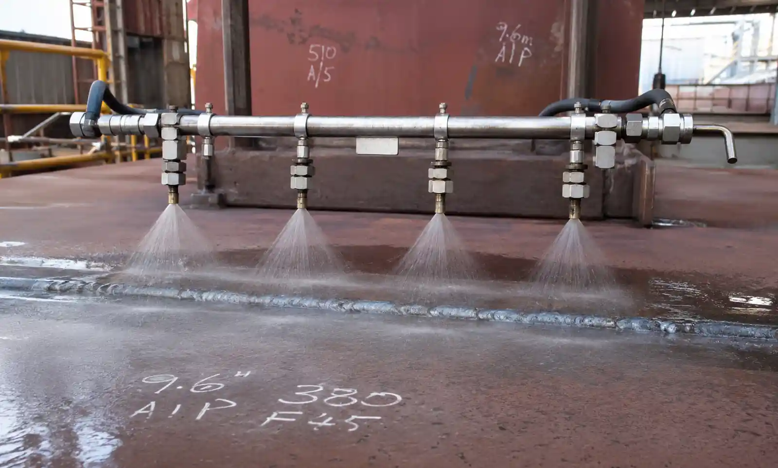
Full Cone Nozzles for Cooling and Fire Protection
Full cone nozzles distribute liquid throughout a circular cross-section, making them ideal for cooling applications where you need uniform thermal management. After welding longitudinal stiffeners onto hull plates, controlled cooling prevents distortion. We position full cone nozzles 24–36 inches above the weld seam, operating at 20–30 PSI to deliver a gentle, uniform mist that manages cooling rate without creating shock cracks.
In fire suppression systems (water mist or deluge), full cone nozzles rated for 80–120 PSI produce 200–400 micron droplets that absorb heat efficiently while minimizing water damage to sensitive equipment in engine rooms or electrical panels.
Hollow Cone and Spiral Nozzles for Tank Cleaning
Hollow cone nozzles concentrate flow at the pattern periphery, creating high-velocity droplets that deliver superior impact force for cleaning. Static hollow cone nozzles work well for smaller tanks (up to 15 feet diameter). For cargo tanks in chemical tankers or product carriers, rotary tank cleaning machines equipped with controlled-angle spiral nozzles provide systematic 3D coverage certified to IMO MEPC.1/Circ.642 standards.
In our testing of crude oil tank cleaning, spiral nozzles operating at 100 PSI with 12–18 GPM flow completed cleaning 40% faster than outdated fixed spray ball systems, reducing off-hire time significantly.
3. Material Selection and Corrosion Resistance
Marine environments expose nozzles to saltwater, acidic cleaning chemicals, abrasive slurries (in blasting or descaling), and high-temperature steam. Material selection directly impacts service life and total cost of ownership.
| Material | Hardness (HRC) | Relative Wear Life | Corrosion Resistance | Cost Multiplier | Best Applications |
|---|---|---|---|---|---|
| Brass | 10–15 | 1x (baseline) | Poor in saltwater, acids | 1x | Freshwater only, low-abrasion |
| 316 Stainless Steel | 20–25 | 3x | Excellent (saltwater, mild acids) | 2–3x | General marine use, chemical wash |
| Hardened Stainless (17-4 PH) | 38–42 | 8x | Very good | 4–5x | Abrasive slurries, high-wear |
| Tungsten Carbide Insert | 70–75 | 25–40x | Excellent | 8–12x | Severe abrasion (descaling, grit) |
| Silicon Carbide Ceramic | 72–78 | 30–50x | Excellent (acids, caustics) | 10–15x | Chemical tank cleaning, acidic |
| Hastelloy C-276 | 22–28 | 5x | Exceptional (HCl, H2SO4, FeCl3) | 20–30x | Concentrated acids, extreme corrosion |
When to Specify Stainless Steel
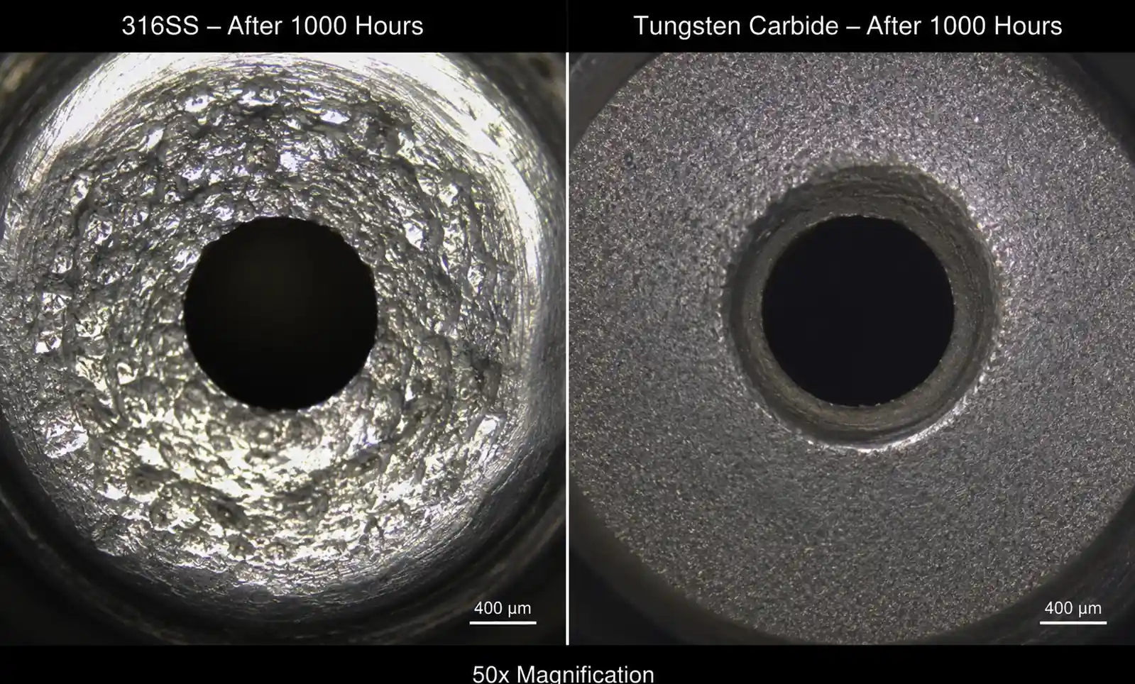
316 stainless steel is the workhorse material for most shipbuilding spray applications. It handles saltwater exposure, alkaline cleaners, and mild acids common in surface prep. For freshwater cooling or rinse systems without abrasive particles, 316SS nozzles easily achieve 8,000–12,000 operating hours before flow rate increases by more than 10% (our typical replacement threshold).
Avoid brass in any marine application—we have seen brass nozzles fail within 400 hours in saltwater spray systems due to dezincification.
Carbide and Ceramic for Abrasive Service
Descaling operations using high-pressure water with entrained mill scale particles destroy stainless nozzles in 200–400 hours. Tungsten carbide inserts extend life to 6,000–10,000 hours under the same conditions. The cost premium (8–12x) pays back within the first year by eliminating frequent replacements and associated downtime.
Silicon carbide offers similar wear resistance and superior acid resistance for tank cleaning nozzles exposed to concentrated sulfuric acid or hydrochloric acid residues. However, ceramic materials are brittle—avoid installations where pressure spikes above rated limits or where mechanical impact during maintenance is likely.
Hastelloy for Extreme Corrosion
In chemical tanker cleaning systems handling high-concentration acids or ferric chloride, standard stainless steel nozzles suffer pitting and stress corrosion cracking. Hastelloy C-276 eliminates corrosion failures but costs 20–30x baseline. We specify Hastelloy only when downtime costs or safety risks justify the premium—typically in high-value specialty chemical carriers.
4. Application-Specific Selection Guide
Shipbuilding encompasses diverse spraying tasks. This section provides nozzle selection criteria for the most common applications.
Steel Plate Surface Preparation and Rinsing
Objective: Remove mill scale, rust, salt, and contaminants before coating.
Recommended Nozzle: Flat fan, 40–65° spray angle, 1.0–2.5 GPM at 40–60 PSI.
Material: 316SS or hardened stainless if recycled water contains abrasive particles.
Spacing: 12–18 inches for 50–80% overlap on conveyor systems.
Key Consideration: Filter water to 100 mesh minimum to prevent clogging. Pre-rinse with freshwater after saltwater exposure reduces chemical consumption in subsequent cleaning stages.
Post-Weld Cooling
Objective: Control cooling rate to prevent thermal shock cracking and minimize distortion.
Recommended Nozzle: Full cone, 60–90° spray angle, 0.5–3.0 GPM at 15–30 PSI.
Material: 316SS (temperature typically below 200°F at spray point).
Droplet Size: 250–500 microns for evaporative cooling without excessive runoff.
Key Consideration: Position nozzles 24–36 inches from weld seam. Use timers to apply intermittent spray (30 seconds on, 60 seconds off) rather than continuous flow for thick sections (>1 inch) to avoid quench cracking.
Anti-Corrosive Coating Application
Objective: Apply uniform primer, intermediate, or topcoat layers within specified thickness range (typically 3–8 mils dry film thickness).
Recommended Nozzle: Air atomizing or airless flat fan, 20–40° spray angle depending on part geometry.
Flow Rate: 0.2–1.5 GPM depending on coating viscosity and desired film build.
Material: Stainless steel wetted parts; tungsten carbide for abrasive coatings (zinc-rich primers).
Key Consideration: Airless systems (3,000–5,000 PSI) deliver better transfer efficiency (60–75%) than air atomizing (40–60%) but produce more overspray. For complex geometries (brackets, pipe penetrations), air atomizing provides better coverage in recesses.
Cargo Tank Cleaning (Chemical Tankers, Product Carriers)
Objective: Remove cargo residues to IMO-specified cleanliness standards; prepare tanks for next cargo or inspection.
Recommended Nozzle: Rotary tank cleaning machine with spiral or controlled-pattern nozzles; 12–25 GPM at 80–150 PSI.
Material: 316SS for petroleum products and vegetable oils; Hastelloy C-276 or silicon carbide for aggressive chemicals (acids, caustics, chlorinated solvents).
Impact Force: Minimum 7–12 N at tank wall (varies by tank size and cargo; refer to IMO MEPC.1/Circ.642).
Key Consideration: Select machines rated for tank dimensions (vertical clearance and horizontal diameter). Under-powered machines may meet impact force at test rig but fail in service due to inadequate throw distance. Verify performance with on-site impact force measurement using load cell at furthest tank corner.
Fire Suppression (Water Mist / Deluge Systems)
Objective: Rapid cooling and oxygen displacement in enclosed spaces (engine rooms, electrical panels, accommodation areas).
Recommended Nozzle: Full cone or hollow cone, depending on system design (low-pressure or high-pressure water mist).
Operating Pressure: Low-pressure systems (12–20 PSI), high-pressure systems (800–1,500 PSI for fine mist).
Droplet Size: 200–400 microns for Class A fires; <200 microns for Class B hydrocarbon fires requiring vapor suppression.
Material: 316SS minimum; verify compliance with IMO FSS Code and applicable flag state regulations.
Key Consideration: Nozzle orifices must remain clear—specify self-cleaning designs or implement quarterly flushing protocols. Use corrosion-resistant materials even in freshwater systems due to long idle periods between tests.
5. Installation and Maintenance Considerations
Proper installation and proactive maintenance extend nozzle service life and ensure consistent spray performance.
Common Installation Mistakes
Insufficient Pipe Diameter Leading to Pressure Drop: A 1/4-inch supply line cannot deliver 5 GPM at rated pressure without excessive velocity loss. For flow rates above 2 GPM, use minimum 3/8-inch or 1/2-inch supply piping and limit velocity to 10 ft/s to minimize pressure drop.
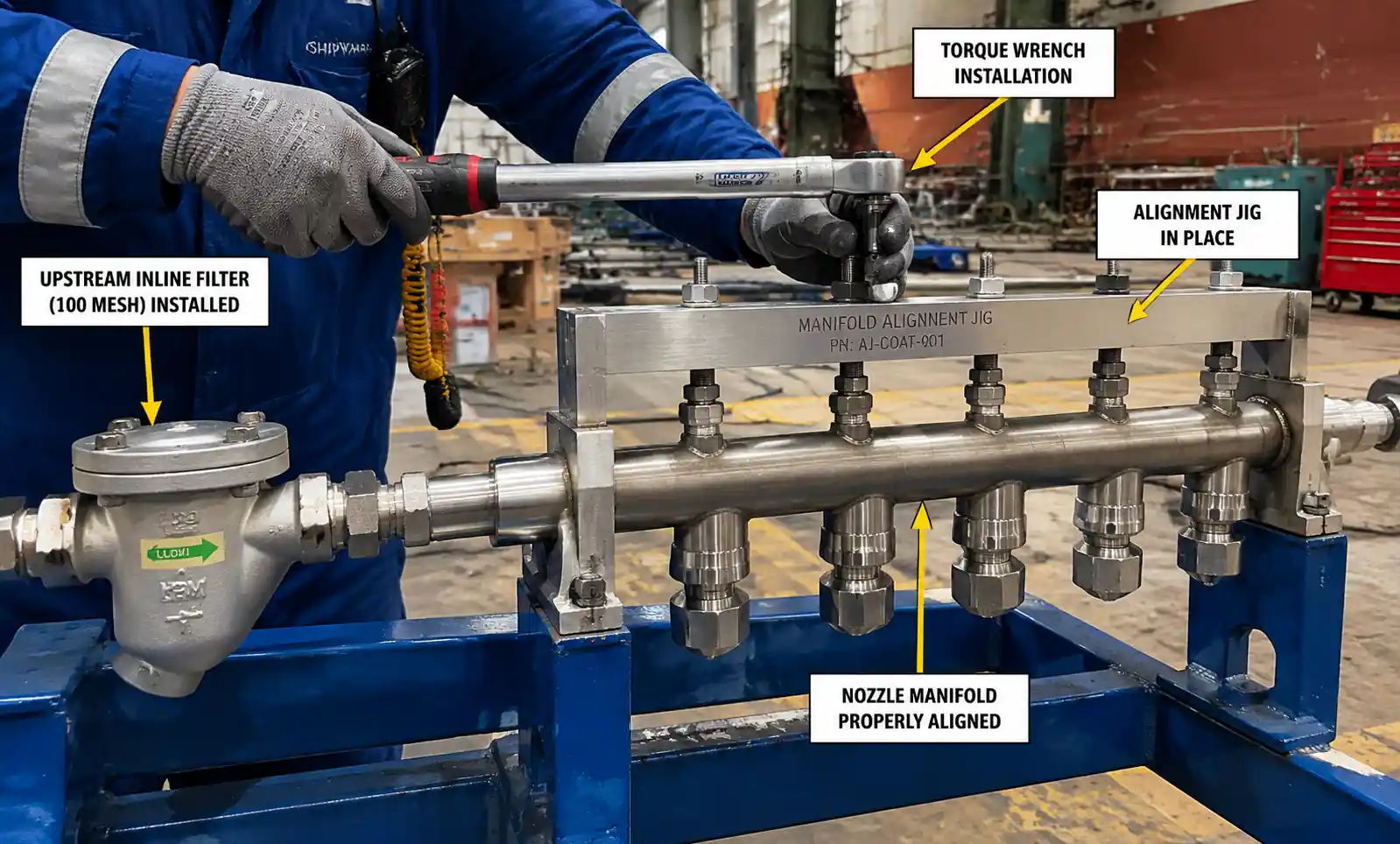
Misaligned Nozzles Creating Coverage Gaps: Even a 5° tilt in nozzle orientation can shift the spray pattern enough to create dry stripes in coating systems. Use alignment jigs during manifold installation and verify coverage with test sprays on kraft paper.
Over-Tightening Causing Body Cracking: Ceramic and carbide nozzles crack if installation torque exceeds specifications (typically 15–25 ft-lb depending on thread size). Use a torque wrench and verify sealing with Teflon tape or appropriate thread sealant rated for operating temperature and chemical compatibility.
Inadequate Filtration Upstream: Failure to install strainers or filters (100–200 mesh depending on orifice size) is the leading cause of premature clogging. In recycled water systems common in shipyards, inline filters prevent weld spatter, paint chips, and rust particles from blocking orifices.
Preventive Maintenance and Performance Monitoring
Flow Rate Verification: Measure flow rate quarterly using a calibrated container and timer. A 10% increase from baseline indicates orifice wear. For critical applications (IMO-certified tank cleaning), replace nozzles when flow exceeds rated tolerance.
Spray Pattern Inspection: Visual inspection on water-sensitive paper reveals spray angle narrowing (indicates partial clogging), distorted patterns (damaged orifice), or uneven distribution (internal blockage). Replace nozzles showing pattern degradation.
Pressure Testing: Record operating pressure at each nozzle position. Rising pressure at constant flow indicates clogging; falling pressure at constant flow suggests orifice enlargement.
Spare Parts Inventory: Maintain 15–20% spares for production-critical nozzles. For specialty materials (Hastelloy, custom ceramic), lead times can extend to 8–12 weeks. Stock common sizes to avoid production delays.
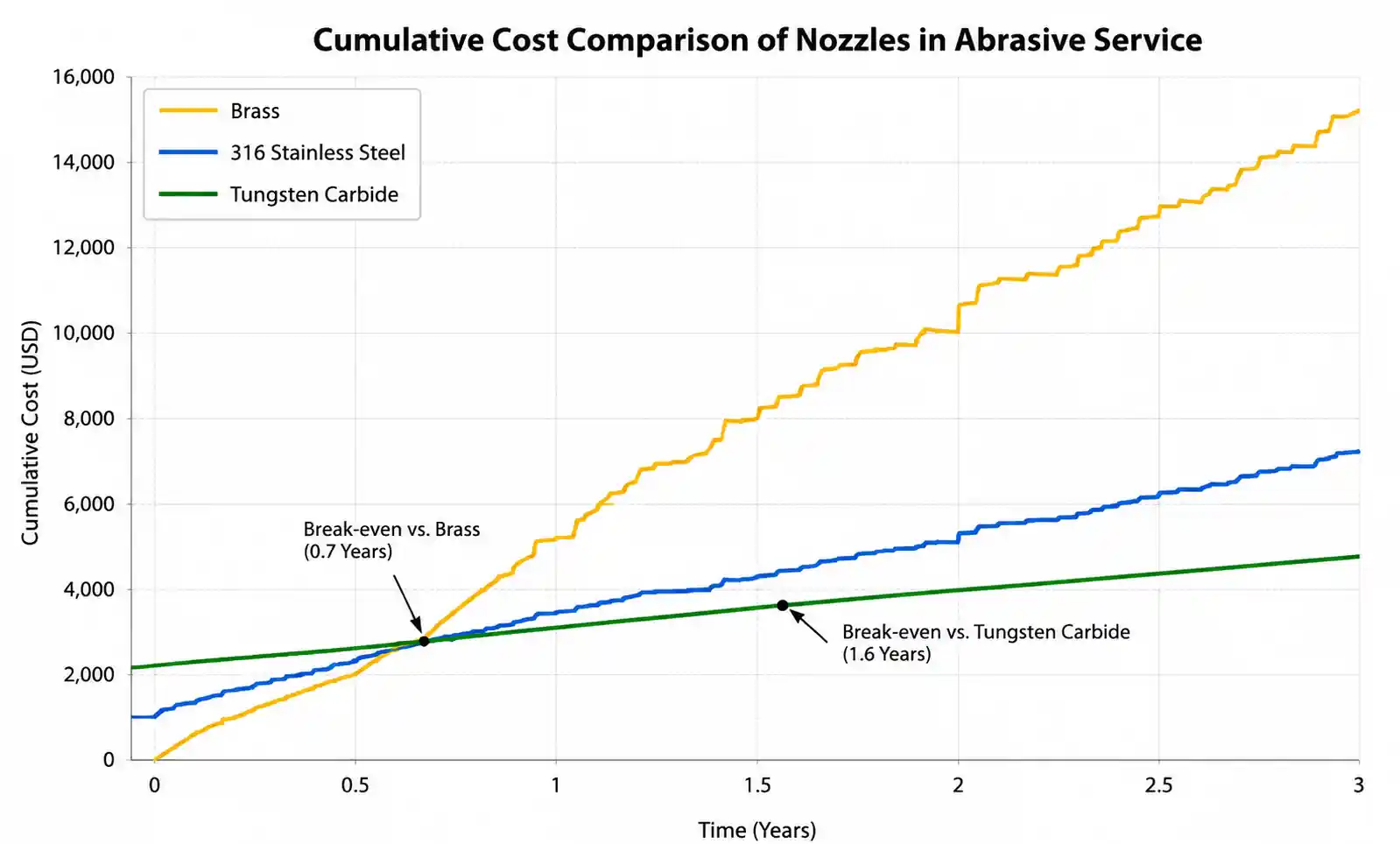
6. Total Cost of Ownership Analysis
Initial nozzle cost is only one component of TCO. Factoring in replacement labor, downtime, and performance degradation often justifies premium materials.
| Scenario | Material | Initial Cost per Nozzle | Service Life (hours) | Replacements per Year (assuming 2,000 hrs/yr operation) | Labor Cost per Replacement | Annual TCO |
|---|---|---|---|---|---|---|
| Baseline | Brass | $8 | 500 | 4 | $50 | $232 |
| Standard Marine | 316SS | $22 | 1,800 | 1.1 | $50 | $79 |
| Abrasive Service | Tungsten Carbide | $150 | 8,000 | 0.25 | $50 | $51 |
Assumptions: Single nozzle installation, $50 labor cost per replacement (1 hour downtime + technician rate), no production loss calculated.
For a coating line with 24 nozzles operating 4,000 hours per year, switching from stainless steel to tungsten carbide represents a $16,800 annual TCO reduction despite 7x higher unit cost. Include production loss costs (typically $200–500 per hour in shipyards) and TCO advantage widens further.
Break-Even Analysis for Carbide Nozzles
Break-even formula:
(Premium nozzle cost - Standard nozzle cost) / [(Standard replacements per year - Premium replacements per year) × (Replacement labor cost + Downtime loss)]
For a descaling system operating 3,000 hours/year:
- 316SS nozzle: $30, life = 400 hours → 7.5 replacements/year
- Tungsten carbide: $180, life = 8,000 hours → 0.375 replacements/year
- Labor + downtime per replacement: $150
Break-even = ($180 - $30) / [(7.5 - 0.375) × $150] = $150 / $1,069 = 0.14 years (1.7 months)
The carbide nozzle pays for itself in under two months and delivers net savings of $919 annually per nozzle position.
7. Frequently Asked Questions
Q: Can I increase flow by simply increasing pressure?
A: Flow increases with the square root of pressure, not proportionally. Doubling pressure from 40 to 80 PSI only increases flow by 41%, not 100%. Over-pressurizing beyond rated limits can damage nozzles and create unsafe operating conditions.
Q: How do I calculate the number of nozzles needed for full coverage?
A: Calculate effective spray width at the target distance: W = 2 × H × tan(θ/2), where H is standoff distance and θ is spray angle. Divide total coverage width by effective width per nozzle, then add 10–20% for overlap. For critical coating applications, validate with test sprays.
Q: What causes spray pattern distortion?
A: Partial clogging (install upstream filtration), orifice damage from pressure spikes or debris impact, erosion wear creating uneven orifice geometry, or manufacturing defects. Inspect and replace nozzles showing distorted patterns—they cannot be restored by cleaning.
Q: Should I clean or replace clogged nozzles?
A: For stainless steel nozzles, ultrasonic cleaning in appropriate solvent can restore performance if clogging is recent and material (dried paint, scale) is removable. For ceramic or carbide nozzles, physical cleaning risks chipping the orifice—replacement is safer. Prevention through filtration is always more cost-effective than cleaning.
Q: How do I specify nozzles for a new tank cleaning machine?
A: Start with IMO impact force requirements for your tank class and cargo type. Work backward to determine flow rate and pressure using machine manufacturer's throw distance curves. Verify material compatibility with worst-case cargo (most corrosive chemical you will handle). Conduct witness testing during commissioning with load cell measurements at multiple tank wall positions.
Q: Can I substitute a different brand's nozzle based on spray angle and flow rate alone?
A: No. Spray angle and flow rate are necessary but not sufficient specifications. Differences in internal vane design affect droplet size distribution, spray uniformity, and pressure-flow characteristics. For critical applications, validate substitute nozzles through side-by-side testing or request performance data (laser diffraction particle size analysis, patternation test results) from the supplier.
Q: What documentation should I require for classification society approval?
A: Type approval certificates, materials test certificates (including ASTM specifications for corrosion resistance), performance test data (flow vs pressure curves, spray angle verification, impact force measurements), and compliance statements for applicable regulations (IMO, SOLAS, flag state requirements). Maintain records for survey inspections.
8. Conclusion and Next Steps
Selecting spray nozzles for shipbuilding applications requires systematic evaluation of spray pattern, flow characteristics, material durability, and application-specific performance criteria. Optimizing these parameters delivers measurable benefits: reduced coating defects, shorter process cycle times, lower maintenance costs, and regulatory compliance.
Key Takeaways
- Match nozzle pattern type (flat fan, full cone, hollow cone) to application geometry and coverage requirements
- Specify materials based on chemical compatibility and abrasion resistance—premium materials deliver lower TCO in harsh service
- Calculate overlap ratio and standoff distance to ensure uniform coverage without gaps or excessive buildup
- Implement preventive maintenance (flow verification, pattern inspection) to detect performance degradation before quality issues arise
- Conduct TCO analysis for high-wear applications—carbide and ceramic nozzles pay back quickly despite higher initial cost
Recommended Actions
-
Audit Current Nozzle Specifications: Review existing installations for material compatibility, wear patterns, and replacement frequency. Identify high-TCO positions for material upgrades.
-
Implement Performance Monitoring: Establish baseline flow rates and spray patterns for critical systems. Schedule quarterly verification testing.
-
Request Application Engineering Support: For complex systems (tank cleaning, automated coating lines, fire suppression), engage nozzle manufacturers' field application engineers to validate selections through on-site testing or computational fluid dynamics modeling.
-
Establish Spare Parts Program: Stock critical nozzles (especially long lead-time specialty materials) to minimize production disruption during planned and unplanned maintenance.
-
Document Specifications: Create detailed nozzle schedules including manufacturer, model number, material, orifice size, spray angle, and operating parameters. Include this documentation in vessel technical files for classification society surveys and crew reference.
For assistance with nozzle selection, performance testing, or troubleshooting existing spray systems, contact our application engineering team for a no-cost process evaluation and specification review.
This guide represents field experience and engineering data from marine fabrication and vessel outfitting installations. Performance parameters and material recommendations should be validated for your specific operating conditions, chemical exposures, and regulatory requirements.